6-1 (E)
UYA-S90SF
Section 6
Block Diagram
6-1. Circuit Description
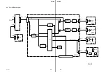
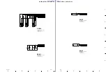
6-1-1. CN-2083 Board
The following description is made with UYA-S90SF
connected to film scanner UY-S90. A signal is passed
through CN201 on the CN-2083 board from CN203 of
UY-S90 so as to receive the power supply. Then, it is
passed through CN202 so as to supply power to the MEC-
13 board. In addition to the power supply, CN201 also
contains a signal line for communicating with the slide
feeder controller on the MEC-13 board and the system
control CPU on the UY-S90 side.
For the power supply to the green power lamp (D251) of
UYA-S90SF, CN202 supplies power to the LE-238 board
via CN203. The lamp does not light when CN202 is not
connected to CN101 on the MEC-13 board. In other
words, it is necessary to confirm whether CN202 is
properly connected to CN101 on the MEC-13 board when
the power lamp of UYA-S90SF does not light.
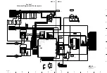
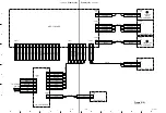
6-1-2. MEC-13 Board
The MEC-13 board is the mechanical control board of a
slider feeder. The MEC-13 board mainly consists of CPU,
flash ROM, and a motor driver circuit.
The CPU of a slider feeder is controlled and operated by
the serial communication from the system control CPU
(called a main unit hereafter) on the UY-S90 side. The
communication control line is buffered by IC101. The
program of CPU that is connected to the CN-2083 board
through CN101 and connected to UY-S90 is stored in flash
ROM (IC106). However, data is supplied by the serial
communication from the main unit and designed to be
rewritten by onboard. Therefore, the program can be
upgraded easily (IC106 must be necessarily set to the latest
version). A motor driver circuit (consisting of IC103 and
IC107) is pulled up so that it is not turned on at all times
when CPU is disabled, and after that, it is connected via an
inverter (IC104).
CPU controls two DC motors according to the instructions
from the main unit. The feed motor on the SU-59 board
carries a slide. During slide carrying, the existence of a
slide can be detected using the sensor on the SE-611 board.
The position motor on the SU-60 board raises or lowers a
cam for control using three sensors on the SE-564 board.
6-1-3. LE-238 Board
The LE-238 board mounts a power lamp (D251). LED
(D251) lights when the power is turned on.
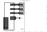
6-1-4. SE-564 Board
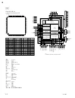
The SE-564 board is a sensor board that detects the cam
position of a slide feeder. This board has three position
sensors (PH231, PH232, and PH233). These sensors are a
transmission-type photointerrupter. They detect the
position when the slit provided in a rotary cylinder reaches
the sensor block. The signal of the sensors is input through
CN102 on the MEC-13 board from CN231 to pins 60, 61,
and 62 of IC105 (controller) and used as a processing
signal.
6-1-5. SE-611 Board
The SE-611 board is a sensor board that detects the
existence of a slide in a slide carrier system. On the SE-
611 board, an infrared light-emitting diode (D241) and
phototransistor (Q241) are arranged so that they are
opposed each other. In this case, the infrared light-
emitting diode and phototransistor constitute a
transmission-type sensor. When a slide is passed through
this sensor, light is shut off and the voltage at the collector
of Q241 increases up to the value near the supply voltage.
This signal is input through CN106 on the MEC-13 board
from CN241 to pin 59 of IC105 (controller) and used to
control a carrier system.
6-1-6. SU-59 Board
The SU-59 board supplies the control power to a feed
motor (M211). The drive signal that is output from IC103
(motor driver M54543L) on the MEC-13 board sent from
CN104 on the MEC-13 board through CN211 on the SU-
59 board so as to control the motor.
6-1-7. SU-60 Board
The SU-60 board supplies the control power to a position
motor (M221). The drive signal that is output from IC107
(motor driver M54543L) on the MEC-13 board sent from
CN105 on the MEC-13 board through CN221 on the SU-
60 board so as to control the motor.

