background image

1-6 (E)

UY
A-S90SF

10 

(GB)

4

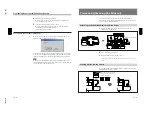
Adjust the prescanned image as required.
When you have set “Mode” to “Prescan all slides (50 slides max),”
select the images to be scanned.

5

Click the Scan button on the preview window.
When the Scan Utility is used, specify the saving method for the
scanned images and click the Save button.
The selected slides are scanned.

To scan more than 50 slides continuously

When you have set “Mode” to “Prescan only first slide (No limit),”  the
following window appears during scanning.

Click the Pause button to temporarily stop scanning.  Then you can insert
more slides into the holder for prescanning on the auto slide feeder.  After
setting the required slides, click the Continue button to restart scanning.

Note

When you have added slides to the holder for prescanning, remove the
scanned slides in the holder for scanning.  If the holder is full of slides, the
ejected slides may clog, causing an error.

Prescanning/Scanning the Slides Continuously

11 

(GB)

Slide attachment (supplied)

Prescanning/Scanning One Slide only

To prescan/scan only one slide, use the supplied slide attachment.
For details on the prescanning/scanning operations, refer to the software
manual of the UY-S90 film scanner.

Attaching the Slide Attachment to the Slide Carrier

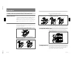
1

Open the lid of the slide carrier and attach the supplied slide
attachment to the slide carrier.

2

Close the lid of the slide carrier.

3

Mount the slide carrier to the film scanner.

For mounting, “Mounting the Slide Carrier to the Film Scanner” on page
5(GB).

Loading a Slide into the Carrier

Insert a slide into the slide attachment with the emulsion side facing you,
and lightly press the slide to the left.

Insert a slide with the emulsion side
facing you and the picture sidelong.

This way

Not this way

Содержание UYA-S90SF

Страница 1: ...AUTO SLIDE FEEDER UYA S90SF SERVICE MANUAL 1st Edition ...

Страница 2: ...rden Um die Gefahr eines elektrischen Schlages Feuergefahr und Verletzungen zu vermeiden sind bei Wartungsarbeiten strikt die Angaben in der Anleitung zu befolgen Andere als die angegeben Wartungsarbeiten dürfen nur von Personen ausgeführt werden die eine spezielle Befähigung dazu besitzen AVERTISSEMENT Ce manual est destiné uniquement aux personnes compétentes en charge de l entretien Afin de réd...

Страница 3: ...inet 2 1 E 2 1 3 Replacement of Main Parts 2 2 E 2 1 4 Cleaning Replacement of Main Roller 2 5 E 2 2 Carrier Assembly 2 5 E 2 2 1 Main Parts Location 2 5 E 2 2 2 Replacement of Main Parts 2 5 E 2 3 Tools 2 7 E 3 Mechanical Operation Description 4 Semiconductor Pin Assignments 5 Spare Parts 5 1 Notes on Repair Parts 5 1 5 2 Exploded Views 5 2 5 3 Electrical Parts List for Boards 5 6 5 4 Parts List ...

Страница 4: ...611 Board 6 1 E 6 1 6 SU 59 Board 6 1 E 6 1 7 SU 60 Board 6 1 E 6 2 Overall Block Diagram 6 3 7 Schematic Diagrams and Board Layouts Schematic Diagrams MEC 13 7 1 CN 1959 7 2 CN 2083 7 2 LE 238 7 2 SE 561 7 2 SE 562 7 2 SE 563 7 2 SE 564 7 3 SE 611 7 3 SU 59 7 3 SU 60 7 3 Frame 7 4 Board Layouts MEC 13 7 6 CN 2083 7 6 LE 238 7 7 SE 564 7 7 SE 611 7 7 SU 59 7 7 SU 60 7 7 ...

Страница 5: ...duct Part No 3 204 878 01 This manual describes the information required for the actual management and operation of this unit Semiconductor Pin Assignments CD ROM Available on request This Semiconductor Pin Assignments CD ROM allows you to search for semiconductors used in Communication System Solutions Network Company equipment Semiconductors that cannot be searched for on this CD ROM are listed ...

Страница 6: ......

Страница 7: ...1 1 E UYA S90SF Section 1 Operating Instructions Reprinted from the operating instructions UYA S90SF 2000 Sony Corporation 3 204 878 01 1 Auto Slide Feeder Operating Instructions GB ...

Страница 8: ...erference at his own expense You are cautioned that any changes or modifications not expressly approved in this manual could void your authority to operate this equipment For the customers in Canada This Class A digital apparatus complies with Canadian ICES 003 3 GB Table of Contents Features 4 GB Checking the Package 4 GB Mounting the Slide Carrier to the Film Scanner 5 GB Mounting the Auto Slide...

Страница 9: ...king materials in case you have to transport the parts in the future Remove the slide carrier and the auto slide feeder when transporting the film scanner Slide carrier 1 Auto slide feeder 1 Slide attachment 1 Replacement rubber rollers 2 CD ROM 1 Operating Instructions 1 Software Licence Agreement 1 Warranty booklet 1 5 GB Mounting the Slide Carrier to the Film Scanner Mounting the carrier Insert...

Страница 10: ...e panel of the film scanner and the cover of the slide feeder connector 2 Mount the auto slide feeder on the film scanner Insert the two projections on the rear of the auto slide feeder into the slits on the film scanner and the connector to the slide feeder connector For easier positioning place the auto slide feeder parallel to the side of the film scanner then fit the square projected part of t...

Страница 11: ...uired and select the frames for scanning 9 GB Auto Focus Only first slide Adjusts the focus only for the first slide set on the auto slide feeder The other slides are prescanned and scanned with the same focus conditions adjusted for the first slide Normally use this mode All slides Adjusts the focus for each slide set on the auto slide feeder Use this mode when you want to adjust the focus precis...

Страница 12: ...g remove the scanned slides in the holder for scanning If the holder is full of slides the ejected slides may clog causing an error Prescanning Scanning the Slides Continuously 11 GB Slide attachment supplied Prescanning Scanning One Slide only To prescan scan only one slide use the supplied slide attachment For details on the prescanning scanning operations refer to the software manual of the UY ...

Страница 13: ... the rubber roller 2 Lift the shaft using the tab on the rear of the lid While pressing up the tab move the stopper to lock 13 GB 3 Insert a new rubber roller and close the lid Make sure the top and bottom of the rubber roller are positioned correctly For more replacement rubber rollers consult your authorized Sony dealer Cleaning inside the Slide Carrier Inside the slide carrier there are 15 roll...

Страница 14: ...ur unit For maximum protection repack the unit as it was originally packed at the factory Specifications Applicable film Slides mounted of 135 film and IX240 film Dimensions Slide carrier Approx 231 135 46 mm w h d 9 1 8 5 3 8 1 13 16 inches Auto slide feeder Approx 80 148 354 mm w h d 3 1 4 5 7 8 14 inches not including projecting part Mass Slide carrier Approx 0 55 kg 1 lb 3 oz Auto slide feeder...

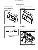
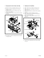
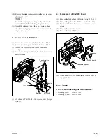
Страница 15: ...H233 PH231 SE 564 board Side A Dust cover BVTP 3x12 BVTP 3x12 BVTP 3x12 Hooks Side cover Hooks CN 2083 board Harness Feet 2 1 2 Removal and Installation of Cabinet 1 Dust Cover 2 Side Cover 1 Remove the eight screws and two feet then remove the four hooks 2 Remove the side cover in the direction indicated by the arrow then remove one harness from the CN 2083 board 3 Attach the side cover in the re...

Страница 16: ... 1 to 3 2 Replacement of MEC 13 Board 1 Remove the side cover Refer to Section 2 1 2 2 2 Remove the top cover and under cover Refer to Section 2 1 2 3 3 Disconnect the five harnesses from the MEC 13 board 4 Remove the three screws then remove the MEC 13 board 5 Attach a new MEC 13 board in the reverse order of steps 1 to 4 3 Top Cover Under Cover 1 Remove the side cover Refer to Section 2 1 2 2 2 ...

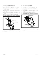
Страница 17: ...nner chassis assembly Refer to Section 2 1 3 3 4 Disconnect one harness from the cam motor 5 Remove the three screws BVTT 3x6 then remove the cam motor bracket block 6 Remove the two screws PS 3x4 then remove the cam motor 7 Attach a new cam motor in the reverse order of steps 1 to 6 3 Replacement of Inner Chassis Assembly 1 Remove the side cover Refer to Section 2 1 2 2 2 Remove the top cover and...

Страница 18: ...ne harness from the roller motor 5 Remove the two screws then remove the roller motor 6 Attach a new roller motor in the reverse order of steps 1 to 5 5 Replacement of SE 564 Board 1 Remove the side cover Refer to Section 2 1 2 2 2 Remove the top cover and under cover Refer to Section 2 1 2 3 3 Remove the inner chassis assembly Refer to Section 2 1 3 3 4 Remove the cam motor bracket Refer to Secti...

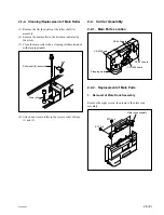
Страница 19: ...then pull out the roller shaft A assembly 2 Remove the main roller in the direction indicated by the arrow 3 Clean the main roller with a cleaning cloth moistended with cleaning liquid 4 Attach a new main roller in the reverse order of steps 1 and 2 2 2 Carrier Assembly 2 2 1 Main Parts Location 2 2 2 Replacement of Main Parts 1 Removal of Plate Rock Assembly Remove the eight screws then remove th...

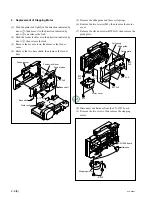
Страница 20: ...r cover 7 Remove the eleven screws BTP2x5 then remove the guide plate 8 Disconnect one harness from the CN 1959 board 9 Remove the two screws then remove the stepping motor 2 Replacement of Stepping Motor 1 Push the plate rock lightly in the direction indicated by arrow 1 then move it in the direction indicated by arrow 2 and release the lock 2 Push the feeder lock lever in the direction indicated...

Страница 21: ...ng the main roller are Cleaning cloth 3 184 527 01 Cleaning liquid 9 919 573 01 10 Remove the plate rock assembly in the reverse order of steps 6 to 9 n Secure the stepping motor temporarily with the two screws B3x3 before attaching the guide plate 11 Attach the slide guide and three coil springs then attach a new stepping motor in the reverse order of steps 1 to 4 3 Replacement of TN 15 Belt 1 Re...

Страница 22: ......

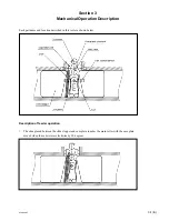
Страница 23: ...tion Each part name and location described in this text are shown below Description of feeder operation 1 The slide placed between the slide stopper and cam plate touches the main roller with the cam plate moved when the cam rotates clockwise by 90 degrees ...

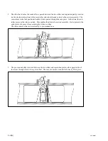
Страница 24: ...passed through the cam plate At that time the sub roller moves as the slide is carried This enables the slide to be carried smoothly It also prevents the optical axis of a sensor from carrying the slide in overlap The slide carried to the carrier assembly is pre scanned once 3 The pre scanned slide is carried between the two rollers and separation plate on the opposite side of the router through w...

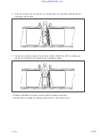
Страница 25: ...e slide is set and the carrying of the next slide is started After the set slide is completely pre scanned the slide shifts to the scanning normal scanning operation Scanning is performed based on the operation opposite to during pre scanning The slide that has completed the scanning operation returns to the position set first http getMANUAL com ...

Страница 26: ......

Страница 27: ...parate CD ROM titled Semiconductor Pin Assignments Sony Part No 9 968 546 xx that allows searching for parts by semiconductor type or ID No The semiconductors in the manual or on the CD ROM are listed by equivalent types Thus the external view or the index mark indication may differ from the actual type Pin assignments and block diagrams are based on the IC manufacturer s data book Index LED Page ...

Страница 28: ...7 P81 P83 RES RXD STBY TCLKA TCLKD VREF WAIT XTAL OUTPUTS A0 A19 AS RD RESO TOCXA4 TOCXB4 TXD WR Ø INPUTS OUTPUTS D0 D7 P60 P80 P90 P92 P94 PA0 PA7 PB0 PB7 SCK TIOCA0 TIOCA4 TIOCB0 TIOCB4 A D TRIGGER ANALOG CRYSTAL INTERRUPT REQUEST MODE INTERRUPT FOR NO MASKING PORT7 PORT8 RESET RECEIVE DATA STANDBY CLOCK REFERENCE VOLTAGE WAIT CRYSTAL ADDRESS BUS ADDRESS STROBE READ RESET OUTPUT COMPARE TRANSMIT...

Страница 29: ...er from those used for the unit These are because of parts common ality and improvement Parts list has the present standardized repair parts 3 Stock of Parts Parts marked with o at SP Supply Code column of the spare parts list may not be stocked Therefore the delivery date will be delayed 4 Harness Harnesses with no part number are not registered as spare parts In need of repair get components sho...

Страница 30: ... 1 31 28 36 36 36 36 24 30 29 7 20 17 36 32 32 36 36 31 36 6 15 32 32 4 32 21 14 32 5 10 16 27 22 35 9 32 26 16 32 32 25 16 32 2 32 3 28 34 36 32 11 12 19 32 36 8 36 B 3x3 PRECISION P2x4 5 PRECISION P2x3 5 PRECISION P2x3 5 5 2 Exploded Views 1 AS Carrier Block ...

Страница 31: ... LOCK CAM 16 3 612 047 01 s BEARING 3 0 17 3 626 621 01 s PLATE GUIDE 18 3 626 622 01 s RETAINER 19 3 626 625 01 s RETAINER SPRING 20 3 626 626 01 s GUIDE SLIDE 21 3 626 627 01 s SPRING COMPRESSION 22 3 626 631 01 s BELT 172TN15 5 0T 23 3 626 632 01 o FEEDER COVER 24 3 626 633 01 o FEEDER BASE 25 3 626 641 01 s ROLLER SUPPLY A 26 3 626 642 01 s ROLLER SUPPLY B 27 3 626 643 01 s ROLLER SUPPLY C 28 ...

Страница 32: ...612 047 01 s BEARING 3 0 114 3 612 136 02 s GEAR 10 0 IDLER 115 3 629 339 02 o SIDE COVER 116 3 629 341 04 o TOP COVER 117 3 629 345 01 o PLATE POSITIONING 118 3 629 350 01 o COVER PAD 119 3 629 351 01 o LOWER ARM 120 3 629 353 01 s GEAR ROLLER 20A 121 3 629 354 01 s GEAR RETAINER 122 3 629 355 02 o SHAFT CAM 123 3 629 356 02 o TOP PLATE No Part No SP Description 124 3 629 363 02 o CENTER CHASSIS ...

Страница 33: ...TING SCREW 207 X 3737 811 1 s WORM BLOCK ASSY 208 1 541 309 11 s MOTOR RF 370C DC 2 59W 209 3 611 868 01 s WHEEL HEAD WORM 210 3 612 047 01 s BEARING 3 0 211 3 612 110 01 s WORM WHEEL SUPPLY 212 3 629 340 01 o UNDER COVER 213 3 629 344 01 s BEARING A POM No Part No SP Description 214 3 629 347 02 s GEAR CAM 30 215 3 629 348 01 s GEAR SECOND 36 216 3 629 364 01 s GEAR ROLLER 28 217 3 734 866 01 s F...

Страница 34: ...6 11 s CAPACITOR CERAMIC 0 1MF 25V F C111 1 126 935 11 s CAPACITOR ELECT 470MF 16V C112 1 164 156 11 s CAPACITOR CERAMIC 0 1MF 25V F C113 1 164 156 11 s CAPACITOR CERAMIC 0 1MF 25V F C114 1 126 934 11 s CAPACITOR ELECT 220MF 16V C117 1 164 156 11 s CAPACITOR CERAMIC 0 1MF 25V F C118 1 164 156 11 s CAPACITOR CERAMIC 0 1MF 25V F C119 1 164 156 11 s CAPACITOR CERAMIC 0 1MF 25V F C120 1 164 156 11 s C...

Страница 35: ... RESISTOR CHIP 0 1 16W 1608 R134 1 216 864 11 s RESISTOR CHIP 0 1 16W 1608 R135 1 216 864 11 s RESISTOR CHIP 0 1 16W 1608 R136 1 216 864 11 s RESISTOR CHIP 0 1 16W 1608 S101 1 570 909 11 s SWITCH TACTIL REFLOW TYPE X401 1 760 606 21 s VIBRATOR CERAMIC SE 561 BOARD Ref No or Q ty Part No SP Description 1pc A 8326 296 A o MOUNTED CIRCUIT BOARD SE 561 CN910 1 566 759 11 o PIN CONNECTOR 4P PH910 8 749...

Страница 36: ...AL SOLDERLESS TO CN251 LE 238 BOARD 1pc 1 569 617 11 o HOUSING CONNECTOR 2P 2pcs 1 569 977 11 o TERMINAL SOLDERLESS HN003 HARNESS SUB S F HARNESS E TO CN105 MEC 13 BOARD 1pc 1 569 195 31 o HOUSING CONNECTOR 2P 2pcs 1 569 193 11 s TERMINAL SOLDERLESS TO CN221 SU 60 BOARD 1pc 1 569 195 31 o HOUSING CONNECTOR 2P 2pcs 1 569 193 11 s TERMINAL SOLDERLESS HN004 HARNESS SUB S F HARNESS B TO CN102 MEC 13 B...

Страница 37: ...PPLIED ACCESSORIES Ref No or Q ty Part No SP Description 1pc A 8326 294 A s ADAPTOR ASSY SLIDE FILM 1pc 3 204 878 01 s MANUAL INSTRUCTION 1pc 7 627 553 58 s SCREW PRECISION P 2X4 5 2pcs 7 685 546 19 s SCREW BTP3X8 5 5 Packing Materials ...

Страница 38: ......

Страница 39: ...tions from the main unit The feed motor on the SU 59 board carries a slide During slide carrying the existence of a slide can be detected using the sensor on the SE 611 board The position motor on the SU 60 board raises or lowers a cam for control using three sensors on the SE 564 board 6 1 3 LE 238 Board The LE 238 board mounts a power lamp D251 LED D251 lights when the power is turned on 6 1 4 S...

Страница 40: ......

Страница 41: ...OSITION MOTOR IC107 L P F LF101 L P F LF102 ROM IC106 IC104 IC104 DATA ADDRESS BUS SENSOR SIGNAL BUFFER IC101 CN202 CN101 12V 5V CN203 CN251 D251 CN103 CN104 CN211 CN105 CN106 Q241 D241 CN102 PH231 PH233 PH232 CN221 CN241 CN231 CN201 TO UY S90 RESET IC IC102 IC105 CPU CN 2083 LE 238 SU 59 SU 60 SE 611 MEC 13 SE 564 M M SERIAL DATA ...

Страница 42: ......

Страница 43: ...SB RD5 6SB RD5 6SB 4 7k 4 7k 4 7k 4 7k 16MHz 0 0 0 0 NM 0 0 0 100k NM NM 10k NM NM 10k 10k 10k 10k 10k 10k 10k 10k 22k 22k 22k 560 NM 10k 10k 47 47 47 47 47 74HC138 M54543L 74HC04 74HC04 74HC04 74HC04 74HC04 74HC04 74HC04 M54543L S 80840ANUP LS541 IS2837 3P 2P 2P 5P 11P 0 1 0 1 50V 0 1 50V 0 1 16V 220µF 0 1 0 1 0 1 0 1 50V 0 1 50V 0 1 16V 220µF 0 1 0 1 10V 470µF F 25V 0 1 10V 470µF F 25V 0 1 16V 2...

Страница 44: ... 5 6 7 8 9 10 11 12 13 14 15 16 17 18 19 20 21 22 23 24 25 26 1 2 3 4 5 6 7 CN903 CN905 CN906 CN901 CN904 GND 5V GND 5V GND 5V GND PROTECT GND FILM PERF0 GND GND SEL1 SEL2 B A DCB DCA GND 5V PROTECT B A B A 24V 24V CAM DISK LLD SLIDE3 SLIDE4 NC NC B A RXD TXD SLIDE3 SLIDE4 SLIDE2 SLIDE1 1 2 3 4 CN910 PH910 PH920 R910 R920 390 1 4W 390 1 4W 1 1 4 3 2 4 3 2 5V GND SLIDE1 SLIDE2 1 2 3 CN930 PH930 R93...

Страница 45: ...D242 Q241 R241 0 1µF 25V F 1000p CH NM NM 3P GL480 RD5 6SB T1 PT480F 330 5V JUM GND 1 2 M C211 CN211 M211 0 1µF 50V 2P NM FEED_1 FEED_2 1 2 M C221 CN221 M221 0 1µF 50V 2P NM POSITION_1 POSITION_2 SE 564 BOARD NO 1 679 703 11 LOT NO 005 B CEPXA125A SE564 02 SE 611 BOARD NO 1 679 704 11 LOT NO 005 B CEPXA125A SE611 02 SU 59 BOARD NO 1 679 705 11 LOT NO 005 B CEPXA125A SU59 02 SU 60 BOARD NO 1 679 70...

Страница 46: ...TXD MD2SCK 5V GND GND 12V 5V GND 1 2 3 4 5 6 7 8 9 10 11 5V JUM GND 1 2 3 CN103 28P MEC 13 BOARD CN 2083 BOARD TO UY S90 CN 203 D SUB 9P CN201 9P CN106 3P CN101 11P CN202 11P GND POSITION_C POSITION_B POSITION_A 5V 5 4 3 2 1 CN102 5P 5V POSITION_A POSITION_B POSITION_C GND 1 2 3 4 5 CN231 5P 5V GND 1 2 CN203 2P SE 564 BOARD FEED_2 FEED_1 2 1 CN104 2P FEED_1 FEED_2 1 2 CN211 2P SU 59 BOARD 5V GND 1...

Страница 47: ... 6 7 8 9 10 11 12 13 14 15 16 17 18 19 20 21 22 23 24 25 26 CN 1959 BOARD 5V SLIDE1 SLIDE2 GND 1 2 3 4 CN901 4P 5V SLIDE1 SLIDE2 GND 1 2 3 4 CN910 4P CN906 26P SE 561 BOARD HN007 5V SLIDE3 GND 1 2 3 CN903 3P 5V SLIDE3 GND 1 2 3 CN930 3P SE 562 BOARD HN008 5V SLIDE4 GND 1 2 3 CN904 3P 5V SLIDE4 GND 1 2 3 CN940 3P SE 563 BOARD HN009 CN905 7P GND B A B A 24V 24V 7 6 5 4 3 2 1 STEPPING MOTOR 3 Frame 2...

Страница 48: ...3 R106 C2 R107 C2 R108 C2 R109 E2 R110 E2 R111 E2 R112 B1 R113 C1 R114 C1 R115 C1 R116 B1 R117 B1 R118 B1 R119 B1 R120 E3 R121 B3 R122 B3 R123 B3 R124 B3 R125 E2 R126 B2 R127 E2 R128 E1 R129 D3 R130 D3 R131 D3 R132 E3 R133 C1 R134 C1 R135 C1 R136 C1 S101 C2 X401 B2 CN 2083 A SIDE SUFFIX 11 CN 2083 B SIDE SUFFIX 11 C101 C102 C103 C104 C105 C106 C107 C108 C109 C110 C111 C112 C113 C114 C117 C118 C119...

Страница 49: ...231 D232 D233 PH231 PH232 PH233 R231 R232 R233 C241 C242 CN241 D242 R241 D241 Q241 C211 CN211 C221 CN221 SE 564 B SIDE SUFFIX 11 SE 564 A SIDE SUFFIX 11 SE 611 A SIDE SUFFIX 11 SE 611 B SIDE SUFFIX 11 SU 59 A SIDE SUFFIX 11 SU 59 B SIDE SUFFIX 11 SU 60 A SIDE SUFFIX 11 SU 60 B SIDE SUFFIX 11 LE 238 A SIDE SUFFIX 11 LE 238 B SIDE SUFFIX 11 ...

Страница 50: ......

Страница 51: ......

Страница 52: ...Printed in Japan Sony Corporation 2000 11 22 Communication System Solutions Network Company 2000 UYA S90SF SY J E 9 955 248 01 ...

Отзывы: