background image

50

Adjusting the Color and Picture Quality


Ad
jus
tment

2

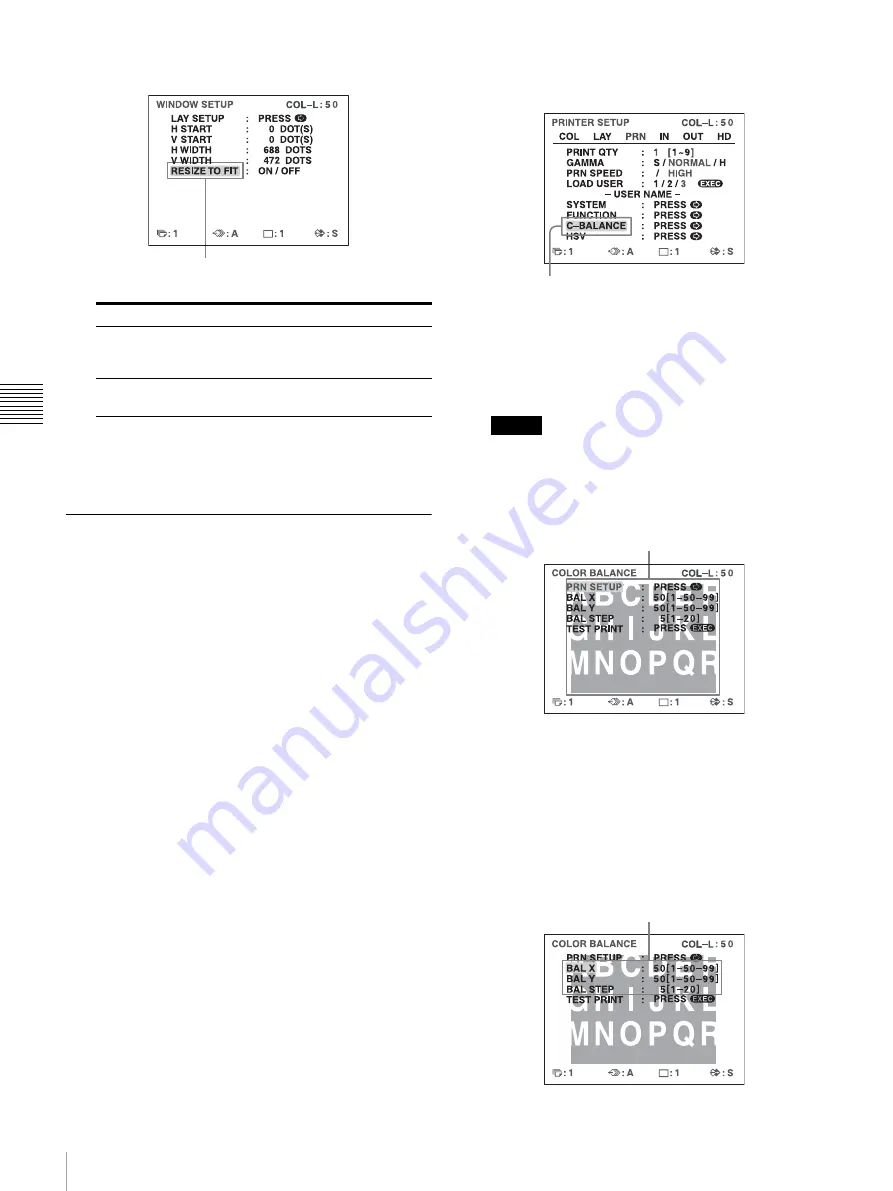
Select RESIZE TO FIT.

The RESIZE TO FIT setting is stored individually for each 
input signal type (SDTV, 1080i, 720p) configured with 
SD/HD SEL in the HDTV SETUP menu.

Adjusting the Color Balance

Use this function to adjust the colors in printouts to match 
the colors displayed on the monitor.
Adjustments to the color balance are not reflected in the 
monitor display.
It is recommended that you adjust the color balance each 
time you load a new set of ink ribbon and paper.
You should use the ink ribbon and paper that are contained 
in the same package as a pair. The color balance may differ 
depending on each pair.
Once you have adjusted and stored the settings, the printer 
operates according to those settings until their values are 
modified.

Before adjusting the color balance

Reset all items on the COLOR ADJUST menu to their 
center values. (See “Adjusting the Printout Color” on 
page 46
.)

1

Display the COLOR BALANCE menu from the 
PRINTER SETUP menu.

The COLOR BALANCE menu appears. The 
highlighted area on the COLOR BALANCE menu 
will be printed to be used for adjusting the color 
balance. You can move this area to any place on the 
video monitor.

Note

If the layout was set to two or four reduced image 
display, the image on which the cursor was positioned 
will be displayed in full size.

When you adjust the color balance for the first time 
after you purchase the printer, the values of BAL X, 
BAL Y and BAL STEP are set to 50, 50 and 5 at the 
factory setting.
When you have adjusted the color balance already, the 
values adjusted previously are displayed on the 
COLOR BALANCE menu.

Setting

When you want to

OFF

Print the image with the printout area 
adjusted on the WINDOW SETUP 
menu

ON

Print the adjusted image to fit to the 
paper

Highlight RESIZE TO FIT in green.

Select C-BALANCE, then press the 

,

 button.

The area that will be captured in memory. 
(This area is highlighted and is two third the 
size of the whole screen.)

The currently adjusted values of BAL X, BAL Y and 
BAL STEP
On this COLOR BALANCE menu, the default values 
(factory settings) are displayed.

Содержание UP25MD

Страница 1: ...Color Video Printer Instructions for Use Before operating the unit please read this manual thoroughly and retain it for future reference UP 25MD 4 162 900 13 1 2010 Sony Corporation ...

Страница 2: ...uct connected to 240 V single phase be sure to connect this product to a center tapped circuit Important safeguards notices for use in the medical environments 1 All the equipments connected to this unit shall be certified according to Standard IEC60601 1 IEC60950 1 IEC60065 or other IEC ISO Standards applicable to the equipments 2 Furthermore all configurations shall comply with the system standa...

Страница 3: ...ion in which it will be used Guidance and manufacturer s declaration electromagnetic emissions The UP 25MD is intended for use in the electromagnetic environment specified below The customer or the user of the UP 25MD should assure that it is used in such an environment Emission test Compliance Electromagnetic environment guidance RF emissions CISPR 11 Group 1 The UP 25MD uses RF energy only for i...

Страница 4: ...mode 2 kV common mode 1 kV differential mode 2 kV common mode Mains power quality should be that of a typical commercial or hospital environment Voltage dips short interruptions and voltage variations on power supply input lines IEC 61000 4 11 5 UT 95 dip in UT for 0 5 cycle 40 UT 60 dip in UT for 5 cycles 70 UT 30 dip in UT for 25 cycles 5 UT 95 dip in UT for 5 sec 5 UT 95 dip in UT for 0 5 cycle...

Страница 5: ...transmitters as determined by an electromagnetic site survey a should be less than the compliance level in each frequency range b Interference may occur in the vicinity of equipment marked with following symbol NOTE 1 At 80 MHz and 800 MHz the higher frequency range applies NOTE 2 These guidelines may not apply in all situations Electromagnetic propagation is affected by absorption and reflection ...

Страница 6: ... addresses given in separate service or guarantee documents Recommended separation distances between portable and mobile RF communications equipment and the UP 25MD The UP 25MD is intended for use in an electromagnetic environment in which radiated RF disturbances are controlled The customer or the user of the UP 25MD can help prevent electromagnetic interference by maintaining a minimum distance ...

Страница 7: ...gnals 45 Matching the Video Monitor Color to the Printer Color 45 Adjusting the Printout Color 46 When a Black Frame or Lines Show up on the Printouts 48 Fitting the Printout to the Paper 49 Adjusting the Color Balance 50 Specifying Colors for Adjustment HSV Adjustment 52 Configuring HDTV Signal Inputs and Outputs 57 Selecting the Input Signal 57 Selecting the Input Signal Type 57 Selecting the In...

Страница 8: ... and can automatically determine the input signal type When you print HDTV signals or display them on a monitor they are output with a 16 9 aspect ratio You can downconvert the signals to SDTV signals with a 4 3 aspect ratio when outputting to a monitor Location and Function of Parts and Controls Front A PRINT indicator Lights while printing is in progress B ALARM indicator Lights when an error su...

Страница 9: ...UP menu also changes in conjunction with each press of this button J PRINT QTY button page 24 Press this button to select the number of copies to print You can select up to nine copies and the current selection is displayed for a few seconds when the button is pressed The PRINT QTY setting in the PRINTER SETUP menu also changes in conjunction with each press of this button You can press this butto...

Страница 10: ... 14 Connects to a computer for controlling the printer G AC IN connector page 12 Connects to the power cord H REMOTE 2 connector stereo mini jack page 14 Connects to an RM 91 Remote Control Unit not supplied or an FS 24 Foot Switch not supplied I REMOTE 1 connector page 14 Connects to an RM 5500 Remote Control Unit not supplied for wired remote control J S VIDEO IN S VIDEO OUT S Video input S Vide...

Страница 11: ...ates the type of printout B Position of the cursor Indicates the position where the cursor is currently placed and where an image will be captured F Memory page display section Indicates the currently selected memory page Memory pages that are currently being printed or memory pages that are queued for printing will blink G Print quantity display section Indicates the number of copies to be printe...

Страница 12: ... be used for printing Notes Turn off the power of each device before attempting to make any connections Connect the AC power cord last Connecting Video Equipment Connect the video equipment providing the video images to be printed Connect the video equipment which will be used in actual printing using the following diagram as a guide Connections for HDTV signal input and output Use the RGB YPbPr S...

Страница 13: ...not be switched b When YPbPr signal is input it is not necessary to connect to the SYNC connector 75 ohm coaxial cable with BNC connectors NTSC PAL switch a to RGB YPbPr SYNC input connectors c to composite video input connector 75 ohm coaxial cable with BNC connectors 75 ohm coaxial cable with BNC connectors Connecting cable with DIN 4 pin connectors to RGB YPbPr SYNC OUTPUTb to S VIDEO OUTPUT a ...

Страница 14: ...EMOTE 1 to REMOTE 2 to AC IN AC power cord not supplied Computer a a When connecting a personal computer select the appropriate baud rate from the SYSTEM SETUP menu See Setting the Baud Rate on page 62 b You can also use the remote control unit as a wireless unit In such a case aim the head of the remote control unit at the remote sensor on the printer With fresh batteries the range of the remote ...

Страница 15: ...T appears on the printer window display 1 Open the ribbon door panel 2 Switch the position of the media switch lever according to the type of ink ribbon being used When using the printer for the first time or when changing the type of ink ribbon to use perform the following to switch the position of the media switch lever 1 Remove the cover 2 Switch the position of the media switch lever 3 Replace...

Страница 16: ...ny slack by turning the gear in the direction of the arrow 2 Slide the ink ribbon straight into the ribbon tray until completely inserted Note Do not touch the white tabs on the sides of the ribbon tray Doing so may result in improper loading of the ink ribbon 5 Slide the ribbon tray straight into the printer until completely inserted 6 Close the ribbon door panel To remove the ribbon tray To remo...

Страница 17: ...ns such as paper jams For details about compatible ink ribbons and paper see Ink Ribbon and Paper on page 66 When the message CHANGE RIBBON appears on the printer window display the ink ribbon is used up Replace the ribbon and load the printer with new paper Be careful when inserting and removing the paper feed tray because it may cause the printer to shift position and fall 1 Press the Z mark on ...

Страница 18: ...heet and to remove any bends in the paper before using it Do not put a mixture of different types of paper in the paper feed tray 3 Remove the protective sheet and close the lid Note Make sure to keep the protective sheet after removing it The reverse side of the protective sheet without printing can be used as a cleaning sheet to clean the thermal head For details about cleaning see Cleaning the ...

Страница 19: ...button When you select COMP When you use the RGB YPbPr INPUT connectors to input the image data select the appropriate type of the input signal 1 2 5 2 3 4 5 Highlight IN in green by pressing the M m or button then the INPUT SETUP menu appears Source signal of the image to be printed Video monitor and printer window display the selected input signal is spelled out Signal from video equipment conne...

Страница 20: ... full size image printout Make sure that the following preparations have been performed and refer to the reference pages as necessary Make sure to perform these preparations while the printer is turned off All connections should have already been made See page 12 Ensure that the appropriate ink ribbon paper set is being used and that they are correctly loaded See pages 15 17 and 66 Select the inpu...

Страница 21: ...n print it again Although the blur should be eliminated the ultimate print quality will be slightly degraded Select the FIELD mode on the LAYOUT SETUP menu See Selecting the memory mode on page 27 Note Usually it is recommended that you make printouts in FRAME mode The default setting is FRAME You can confirm the memory mode setting on the bottom part of the video monitor To change the image captu...

Страница 22: ... press the DISPLAY button again See Erasing the Screen Display on the Video Monitor on page 38 You can also erase the information about ink ribbon and paper See Displaying the Ink Ribbon Type and Remaining Amount of the Ink Ribbon on page 62 If a black line appears on the printout Sometimes a black line appears on the printout although it does not appear on the video monitor This black line can be...

Страница 23: ...set selected in step 3 6 Press the PRINT button The printer makes printouts according to the user set selected in step 3 Making Multiple Copies of Identical Printouts You can make up to 9 copies of identical printouts Setting the printout quantity The following two methods are available to set the number of printouts Using the PRINT QTY button Using the menu You can change the designated number of...

Страница 24: ...umber reaches 1 if the button is pressed again it goes up to 9 Setting the printout quantity using the menu 1 Display the PRINTER SETUP menu according to the operations of step 1 described in Making Printouts with the Desired User Set Number on page 23 2 Select PRINT QTY by pressing the M or m button 3 Select the desired number of copies by pressing the or button 4 Press the MENU button The normal...

Страница 25: ...he number of usable memory pages depend on the type of printouts and settings See Memory page on page 28 1 Select the desired memory page by pressing the MEMORY PAGE button Pressing the MEMORY PAGE button switches the memory page 2 Press the CAPTURE button at the instant the image you want to print appears on the screen 3 Press the PRINT button The image captured in step 2 is queued The image is p...

Страница 26: ...field mode To make printouts it is first necessary to capture the image in memory When capturing an image there are two ways to use the memory one is called frame mode and the other is called field mode Frame mode An image is captured in a memory area Printouts with high resolution can be obtained Printout of a full size image Printout of two reduced images Printout of four reduced images xxxxxxxx...

Страница 27: ...memory mode is fixed at FRAME mode appears for the MEMORY setting in the LAYOUT SETUP menu and FIELD mode is not available Video monitor Printout A quickly moving subject can be printed with less blurring The image displayed on the video monitor is captured in memory page A1 1 4 1 2 3 Mode Contents FRAME We recommend that whenever possible you print in this mode FIELD Select this mode to reduce bl...

Страница 28: ...720p cannot coexist on the same multiple reduced image screen If you change the input signal type with the SD HD SEL setting in the HDTV SETUP menu the images stored in the memory will be overwritten the next time you capture images Selecting a memory page Press the MEMORY PAGE button repeatedly until the desired memory page appears Usable memory page Type of reduced images to be captured in memor...

Страница 29: ...ew seconds after which it disappears 2 Select the type of reduced images to be captured in memory by pressing the MULTI PICTURE button while the screen which appears in step 1 is displayed Press the MULTI PICTURE button repeatedly until the color of the type of reduced images to be captured in memory turns green on the video monitor or until the type of reduced images to be captured in the memory ...

Страница 30: ... button The PRINTER SETUP menu appears again Making a printout with multiple reduced images This subsection explains how to make printouts of multiple reduced images taking as an example the making of a printout of four reduced images Before making the printout of four reduced images Confirm the printout color quality using for example the LOAD COLOR number See page 46 Set the layout to four reduc...

Страница 31: ...g of AUTO LIVE in the FUNCTION SETUP menu See page 30 When the image captured in memory is kept being displayed go to step 3 When the source image is displayed go to step 4 3 Press the SOURCE MEMORY button The source image appears on the video monitor 4 Repeat steps 2 and 3 until you have captured four images when the memory image remains on the video monitor Repeat step 2 until you have captured ...

Страница 32: ...n page 27 then print it again Although the blur should be eliminated the ultimate print quality will be slightly degraded Note Usually it is recommended that you make printouts in FRAME mode Check the setting on the LAYOUT SET UP menu Making a printout with white borders The unit allows you to decide whether or not the images are printed with white borders Note This setting is also effective for t...

Страница 33: ...entered characters are displayed here Non text caption entry operations ON displayed when printing with a caption OFF displayed when printing without a caption Indicates the character selected in the character entry area Indicates the position where the character is to be input in the character display area Character entry area The character or symbol where the cursor is located is highlighted in ...

Страница 34: ...ton For example when the cursor is positioned at N pressing the button results in the cursor moving to O at the left end on the next line To select either capital letters or small letters You can change the characters in the character entry area from capital letters to small letters or vice versa 1 Highlight SHIFT in green by pressing the M m or button on the video monitor Or display SHIFT or shif...

Страница 35: ... entered character without changing the number of characters You can replace a previously entered character with a new one 1 Position the green cursor at the character to be replaced by performing the operations explained in step 4 2 Overwrite the invalid character with the correct character by performing the operations explained in steps 5 and 6 The previously entered character is replaced with t...

Страница 36: ... one or all of the memory pages Whether the images of all memory pages or only a single memory page are deleted depends on the setting of CLEAR in the FUNCTION SETUP menu As the STOP CLEAR button functions as the STOP button when printing is in progress images cannot be deleted while printing is in progress Setting the Function of the STOP CLEAR Button 1 Display the FUNCTION SETUP menu according t...

Страница 37: ...memory image appears without deleting images in the memory pages In this case press the STOP CLEAR button again All images stored in the printer are cleared An image which is being printed cannot be cleared Deleting images in a certain memory page Before deleting images Set CLEAR to PAGE in the FUNCTION SETUP menu 1 Press the SOURCE MEMORY button when the source image is displayed on the video mon...

Страница 38: ...operation is the same regardless of whether those characters are displayed on the video monitor Since the same characters are displayed in the printer window display perform operations watching them in the printer window display For detailed information on displaying the ink ribbon type and the remaining amount of the ink ribbon see Displaying the Ink Ribbon Type and Remaining Amount of the Ink Ri...

Страница 39: ...er characters are displayed on the video monitor by changing DISPLAY to ON or OFF in the OUTPUT SETUP menu The setting of the DISPLAY button also changes according to the setting of DISPLAY in the OUTPUT SETUP menu and vice versa When you want to see an image that is hidden below a menu You can erase the menu temporarily while holding the DISPLAY button down Note The error messages are always disp...

Страница 40: ...ssage display function 61 Setting the baud rate for computer communication 62 Selecting whether or not the operation and error tones sound 61 Adjusting the contrast of printouts 45 Printing menu configurations 62 Registering user settings 62 USER NAME Editing the user name 62 FUNCTION SETUP Selecting the image which appears after storing the image into memory the source image or the memory image 3...

Страница 41: ...NTER SETUP menu CAPTION menu SYSTEM SETUP menu INPUT SETUP menu USER NAME menu OUTPUT SETUP menu FUNCTION SETUP menu COLOR BALANCE menu Normal screen Press the MENU button For reference pages of each menu see the table on Functions That Can be Set on Menus on page 40 HSV menu HDTV SETUP menu ...

Страница 42: ...rsor to the top line by pressing the M or m button 2 Display the desired menu by pressing the or button Example To display the PRINTER SETUP menu 1 2 3 4 EXEC button The menu currently displayed on the screen is lit in green The name of the menu currently displayed appears in capital letters The cursor is not positioned on the top line Highlight PRN in green by pressing the or button then the PRIN...

Страница 43: ...in capital letters by pressing the or button Selected item Item that cannot be changed when is displayed at the selection 1 is selected for MULTI PIX on the LAYOUT SETUP menu SEPARATE LAYOUT SETUP menu COMP is selected for INPUT SEL on the INPUT SETUP or HDTV SETUP menu HUE INPUT SETUP menu COMP is selected for INPUT SEL on the INPUT SETUP or HDTV SETUP menu and 720p is selected for SD HD SEL on t...

Страница 44: ...ETUP menu To display the SYSTEM SETUP sub menu Select SYSTEM by pressing the M or m button then press the button The SYSTEM SETUP menu appears To return from the sub menu Select the menu on the top line then press the button The current setting value The setting value increases every time you press button and decreases every time you press the button The current setting value Highlight SYSTEM in g...

Страница 45: ...the input signal using the IRE item in the SYSTEM SETUP menu The selected IRE is displayed in three digits Notes Do not compensate for the input signal too much Doing so results in the whole of the printout becoming dark To have the adjustment result reflected in the printout you need to capture a new image Matching the Video Monitor Color to the Printer Color To match the color of the monitor ima...

Страница 46: ...menu again 7 Adjust the monitor while comparing the printout with the image on the monitor Adjusting the Printout Color You can adjust the printout quality by adjusting the color intensity printout contrast and sharpness and tone GAMMA of the printout Adjusting the color intensity contrast and sharpness You can store up to three types of settings and manage these settings using the LOAD COLOR numb...

Страница 47: ...the sharpness to any of 15 steps from 1 to 15 A setting of step 8 corresponds to the standard sharpness default setting COLOR ADJUST menu Items to be used for adjusting the color intensity Items to be used for adjusting the contrast Items to be used for adjusting the sharpness Menu Adjustment item Adjustment range When you want to Button to be pressed Adjustment direction on the menu CYN RED 7 to ...

Страница 48: ...er to green on the COLOR ADJUST menu On the printer window display display the desired LOAD COLOR number The settings of the currently selected LOAD COLOR number are displayed The printout is made according to the setting of the selected LOAD COLOR number as long as you do not modify those settings Adjusting the tone of the printout You can adjust the tone so that the details in the white or black...

Страница 49: ...o defaults For H START H WIDTH V START and V WIDTH items you can reset the values to defaults in pairs To reset the values for vertical settings position the cursor at either V START or V WIDTH and then press the and buttons simultaneously To reset the values for horizontal settings position the cursor at either H START or H WIDTH and then press the and buttons simultaneously Screen position and s...

Страница 50: ...y the COLOR BALANCE menu from the PRINTER SETUP menu The COLOR BALANCE menu appears The highlighted area on the COLOR BALANCE menu will be printed to be used for adjusting the color balance You can move this area to any place on the video monitor Note If the layout was set to two or four reduced image display the image on which the cursor was positioned will be displayed in full size When you adju...

Страница 51: ... color balance This print operation can also be performed by pressing the PRINT button while the COLOR BALANCE menu is displayed Example of the actual color change in the test print 5 Select the image which has the best color balance among the nine images If you want to change the color balance after you see the printout adjust the color balance again referring to To readjust the color balance on ...

Страница 52: ...in Adjusting the Color Balance on page 50 3 Select the image with the best color balance among the 9 images If there is not the image with the best color balance repeat steps 1 and 2 until you have obtained the best color balance 4 Go back to step 6 in Adjusting the Color Balance on page 50 Specifying Colors for Adjustment HSV Adjustment Use this function to select a specific color within printout...

Страница 53: ...of the source image move the highlighted area by pressing the M m or button while holding down the DISPLAY button 3 Press the CAPTURE button The image captured in memory appears 4 Specify the color to adjust Specify the color with COLOR SEL Highlight HSV in green by pressing the M or m button then press the button COLOR SEL Description RED R Y Specifies red for adjustment When adjusting the INTENS...

Страница 54: ...value of specified color V VALUE value of specified color GRN G C Specifies green for adjustment When adjusting the INTENSITY the hues between green and cyan G C are specified CYN C B Specifies cyan for adjustment When adjusting the INTENSITY the hues between cyan and blue C B are specified BLU B M Specifies blue for adjustment When adjusting the INTENSITY the hues between blue and magenta B M are...

Страница 55: ...f RED R Y is selected for COLOR SEL for example the hue of colors between red and yellow is more red when the slider is closer to the right and more yellow when closer to the left This value is used as a base parameter for HSV adjustment printouts Data is stored separately for each color selected with COLOR SEL R Y Y G G C C B B M M R SATURATION Adjusts the saturation of the color selected with CO...

Страница 56: ...arameter values of the image that is the most appropriate among the nine images by using the or button You can select whether to perform precise adjustments or broad adjustments by changing the STEP value To perform precise adjustment To perform parameter adjustment within the current parameter range reduce the current STEP value To perform broad adjustment To perform parameter adjustment beyond t...

Страница 57: ...e SD HD SEL is set to AUTO Note Automatic input signal detection is not possible for equipment connected to the VIDEO IN and S VIDEO IN connectors so be sure to select an input signal under INPUT SEL Selecting the Input Signal Format Select the format for HDTV signal input Note on output signals during HDTV signal input When OUTPUT SEL is set to HD signals are output in the format you select here ...

Страница 58: ...using the SD CONV menu item that follows Even if you choose to downconvert to SDTV signals with this setting images will still be printed in a 16 9 aspect ratio Note on output formats When HD is selected here signals are output in the format selected under HD FORMAT When SD is selected here signals are output in the format you select under the INPUT FORM setting of the INPUT SETUP menu 1 Display t...

Страница 59: ...e HDTV image to fit the SDTV screen size while preserving the original aspect ratio Mattes black bars appear above and below the image The entire HDTV image is output without changes to its shape but objects appear smaller in size Crop Crops the left and right edges of the HDTV image Objects located in the left and right edges of the HDTV image are not output Squeeze Compresses the HDTV image hori...

Страница 60: ...hat does not have a print queue When the current memory becomes full previously captured images will be overwritten CAP STOP b CAPTURE STOP Each press of the switch captures an image to memory When the last memory page is reached the HIT ANY KEY message appears and image capturing is disabled BACK SP a Each press of the switch moves the cursor on the reduced image screen to the previous position P...

Страница 61: ...l head cleaning This message appears for approximately 6 seconds after you press the POWER switch to turn on the printer 1 Display the SYSTEM SETUP menu from the PRINTER SETUP menu 2 Select CLEAN DISP then select whether to display the message Selecting Whether the Operation and Error Tones Sound Whenever you press a button on the front door the operation tone sounds one time When an error occurs ...

Страница 62: ... and the remaining amount are to be displayed on the monitor Ink ribbon information Registering a User Set You can store up to three settings of all the printer specifications set or adjusted by using the buttons or the menu and store those settings as a user set The printer retains these setting even if you turn off the power Thus different operators can make printouts with different settings by ...

Страница 63: ...al settings of user set 1 and register the modified set values as user set 2 1 Select user set 1 from the LOAD USER item on the PRINTER SETUP menu 2 Press the EXEC button to execute the selected user set 1 3 Modify the recalled set values 4 Select 2 from the SAVE USER item on the SYSTEM SETUP menu 5 Press the EXEC button The set values modified in step 3 are registered as user set 2 To copy the ex...

Страница 64: ...ltaneously press and the MENU button The printer operation sound continues for approximately 4 seconds and the message PLEASE WAIT appears on the printer window display 3 When the printer operation sound stops and the message TRANSPORT MODE appears in the display press the POWER switch to turn off the printer The thermal head is locked Note If the message PLEASE REMOVE RIBBON appears on the printe...

Страница 65: ...been used as a cleaning sheet do not use it again 3 Insert the paper feed tray into the printer 4 Load the thermal head cleaning cartridge into the printer When an ink ribbon is loaded in the printer remove it before loading the thermal head cleaning cartridge The procedure is the same as loading an ink ribbon For details see Loading the Ink Ribbon on page 15 Once the thermal head cleaning cartrid...

Страница 66: ...paper 100 144 mm with 40 sheets each About the Color Printing Pack UPC 21S UPC 21L and Laminate Color Printing Pack UPC 24SA UPC 24LA Notes When the paper runs out replace both the paper and the ink ribbon Use the ink ribbon and the paper in the carton as a set Do not mix with other varieties of ink ribbon or paper Since like other color dyes the dyes used in this ink ribbon may discolor in time t...

Страница 67: ...gressive Input connectors RGB YPbPr BNC 3 0 7 Vp p SYNC ON G 0 3 Vp p sync negative SYNC BNC 1 0 3 to 4 Vp p sync negative S VIDEO 4 pin mini DIN 1 Y 1 Vp p sync negative C 0 286 Vp p NTSC 0 3 Vp p PAL VIDEO BNC 1 1 Vp p sync negative AC IN for power input Output connectors RGB YPbPr BNC 3 0 7 Vp p SYNC ON G 0 3 Vp p sync negative SYNC BNC 1 0 3 to 4 Vp p sync negative S VIDEO 4 pin mini DIN 1 Y 1...

Страница 68: ...ammable anesthetic mixture with air or with oxygen or nitrous oxide Mode of operation Continuous Item Description MIN TYP MAX Unit Remark tRPW Remote control pulse width 100 mSEC VRP Remote control pulse level 5 V TTL level MIN BUSY GND Notes Always verify that the unit is operating properly before use SONY WILL NOT BE LIABLE FOR DAMAGES OF ANY KIND INCLUDING BUT NOT LIMITED TO COMPENSATION OR REI...

Страница 69: ...display window is not set correctly tAdjust the brightness of the printer window display using the LCD CNTR item on the SYSTEM SETUP menu See page 61 The printer does not print An error message appears on the display tPerform the steps described in Error Warning Messages on page 71 Paper that cannot be used with this printer has been loaded tLoad the correct paper Use only ink ribbons and paper fo...

Страница 70: ... and the message CHANGE RIBBON appears on the printer window display The ink ribbon has been used up tReplace the ink ribbon page 15 Do not reuse the ejected paper There are marks and stripes on the print side The thermal head is dirty tPerform thermal head cleaning page 65 Symptom Possible causes and remedies ...

Страница 71: ... any jammed paper from the printer See page 74 In some cases this message may remain even after the jammed paper is removed To clear the message try removing the paper feed tray and reinserting it with paper loaded inside The base plate of the printer is detached tAttach the base plate securely See page 75 CHECK PAPER PROCESS nn CHECK PAPER nn PROCESS CHECK PAPER LOAD nn CHECK PAPER nn LOAD CHECK ...

Страница 72: ...e 65 Error message Possible causes and remedies On the video monitor On the printer window display Warning message Possible causes and remedies On the video monitor On the printer window display HIT ANY KEY HIT ANY KEY This message appears when the remote control unit is used in CAP STOP CAPTURE STOP mode and when the printer stops capturing images once images have been captured to all memory page...

Страница 73: ... The printer starts printing automatically CLEAN HEAD CLEAN HEAD The thermal head requires cleaning tRefer to Cleaning the thermal head and the internal rollers on page 65 and clean the head You can select whether to display this message with the CLEAN DISP setting in the SYSTEM SETUP menu See page 61 PLEASE REMOVE RIBBON PLEASE REMOVE RIBBON You attempted to enter TRANSPORT MODE with an ink ribbo...

Страница 74: ...m cannot be cleared on page 74 3 Load the paper properly Notes Do not reuse the paper removed in step 2 Only use paper from the printing packs recommended for this printer 4 Insert the paper feed tray into the printer If a paper jam cannot be cleared Follow the steps below to open the base plate on the printer and clear the paper jam Notes Before clearing a paper jam with the following procedure p...

Страница 75: ...uring the base plate 5 Lift up the base plate and remove it from the printer 6 Carefully clear the jammed paper 7 Reattach the base plate V Note The printer cannot print with the base plate removed If a paper jam still cannot be cleared Consult your Sony dealer Do not attempt to remove the paper by force ...

Страница 76: ...Sony Corporation ...

Отзывы: