SRS-T70
– 5 –
– 6 –
SECTION 3
DIAGRAMS
3-1.
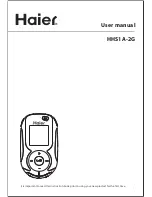
BLOCK DIAGRAM
AMP BOARD, JACK BOARD
PRECAUTION ON ROUTING THE LEAD WIRES
05
•
SIGNAL PATH
: LINE INPUT
S1 (1/4)
S1 (2/4)
S1 (3/4)
S1 (4/4)
B+
SP1
(L-CH)
SP2
(R-CH)
P1
(LINE INPUT)
POWER AMP
IC1
OUT1
IN1+
POWER
AMP
19
12
OUT2
IN2+
POWER
AMP
MUTING
Q1
MUTING
Q2
2
9
POWER AMP
IC2
OUT1
IN1+
POWER
AMP
19
12
OUT2
IN2+
POWER
AMP
2
9
+
+
JK1
DC IN 9V
!
DRY BATTERY
SIZE “AA”
(IEC DESIGNATION R6)
4PCS. 6V
D2
POWER
S1
POWER
OFF/DIRECT
ON
switch knob
S1
Note: When mounting the AMP board,
align the position of switch (S1)
and the switch knob.
3
AMP board
2
two screws
(P2
×
5)
1
Remove four solders
of speaker unit
(SP1/SP2) leads.
1
Remove three solders
of cord (with plug).
1
Disconnect three soldered lead wire,
two (yellow, brown) from the JACK board
and one (red) from plus battery spring.
(For the colors of lead wires and
“PRECAUTION ON ROUTING THE LEAD WIRES”,
see the following figure.)
2
two screws
(P2
×
5)
3
JACK board
1
Disconnect three solders lead wire,
two (yellow, brown) from the AMP board
and one (black) from minus battery spring.
(For the colors of lead wires and
“PRECAUTION ON ROUTING THE LEAD WIRES”,
see the following figure.)
AMP board
GRN
NATURAL
RED
WHT
NATURAL
RED
BLK
lead wire
(speaker unit (SP2)
(R ch)
y
AMP board)
lead wire
(speaker unit
(SP1) (L ch)
y
AMP board)
lead wire (brown)
(AMP board
y
JACK board)
lead wire
(JACK board
y
minus battery spring)
lead wire (red)
(AMP board
y
plus battery spring)
lead wire (yellow)
(AMP board
y
JACK board)
cord (with plug)
Note: Put a knot of the cord
(with plug) into a
groove of rear case.
rear case
JACK board
Note: The lead wires could be pinched between front case
and rear case, resulting in cut-off.