,,-,.,.
.
ervlce
ORDER NO. AD9301003CO
an~ual
Cassette Deck
Dolby NR-Equipped
Stereo Double Cassette Deck
*
DOl
DOLBY
B.e
NR HX PRO
I
-
NEW MECHANISM FOR RS.TR979 (AR.1)
~
SPECIFICATIONS
,
.
CASSETTE
DECK SECTION
Deck system
Track system
Recording system
Bias frequency
Erasing system
Heads
DECK 1
Stereo cassette deck
4-track, 2-channel
AC bias
80kHz
AC erase
..-...
Recording/Playback head (Permalloy) x 1
Erasing head (Double-gap ferrite) x 1
Recording/Playback head (Permalloy) x 1
Erasing head (Double-gap ferrite) x 1
DECK 2
Motors
DECK 1
Capstan/reel table drive (DC servo motor) x 1
Reel table drive (DC motor) x 1
Capstan/reel table drive (DC servo motor) x 1
Reel table drive (DC motor) x 1
4.8cm/sec. (1-7/8ips)
DECK
2
Tape speed
Wow and flutter
For (PP)area
For others
0.1 % (WRMS)
0.07% (WRMS)
i:0.2%
(DIN)
\
Fast forward and
rewind
times
Approx. 45 seconds with C-60 cassette tape
Frequency response (Dolby NR off)
NORMAL
For (PP) area
For others
crO2
For
(PP)
area
For others
......
40Hz-15kHzi:3dB
20 Hz -17 kHz
20Hz-16kHz
(DIN)
40Hz-15kHzi:3dB
20 Hz -17 kHz
20Hz-16kHz
(DIN)
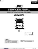
Technics
I
~
RS-TR979
Area
Colour
I
(K)... Black Type
*
HX Pro headroom extension originated
by Bang
Olufsen and manufactured
under license from Dolby
laboratories
Licensing
Corporation.
"DOLBY", the double.D symbol, and "HX PRO" are
trademarks
of Dolby laboratories
Licensing
Corporation.
METAL
40Hz-16kHzi:3dB
For (PP) area
20Hz-18kHz
For others
20Hz-17kHz
(DIN)
SIN
(Signallevel=max
recording level, CrO2 type tape)
NR off
56dB (A weighted)
Dolby B NR on
66dB (A weighted)
Dolby C NR on
74dB (A weighted)
Input sensitivity
and impedance
REC (IN)
Output
voltage
and Impedance
PLAY (OUT)
HEADPHONES
100mV/47kQ
500mV/500Q
37.5mV/(8Q)
(Loadimpedance8Q-600Q)
.GENERAL
Power
consumption
Power supply
For (PP) area
For
(GC)area
For others
Dimensions (Wx H x D)
430x 145x 280mm(16-15/16"x 5-23/32"x 11-1/32")
5.3kg (11.7Ib.)
28W
AC 60Hz, 120V
AC 50/60
Hz,
110V/127V/220V/240V
AC 50/60 Hz, 230V-240V
Weight
Note:
Specificationsare subjectto changewithout notice.
Weightand dimensionsare approximate.
t
lOC,:.
1.1 1_1
-
tv'1
A.STIiR C'-oP'f -
Suffix for
Area
Colour
Model No.
(PP)
U.S.A./Canada.
(EB)
Great Britain.
(EG)
Germany, Italy and
(K)
Continental
Europe.
Asia, Latin America,
(GC)
Middle Near East
and Africa.