


1-9
VPL-PX20/PX30
16
(GB)
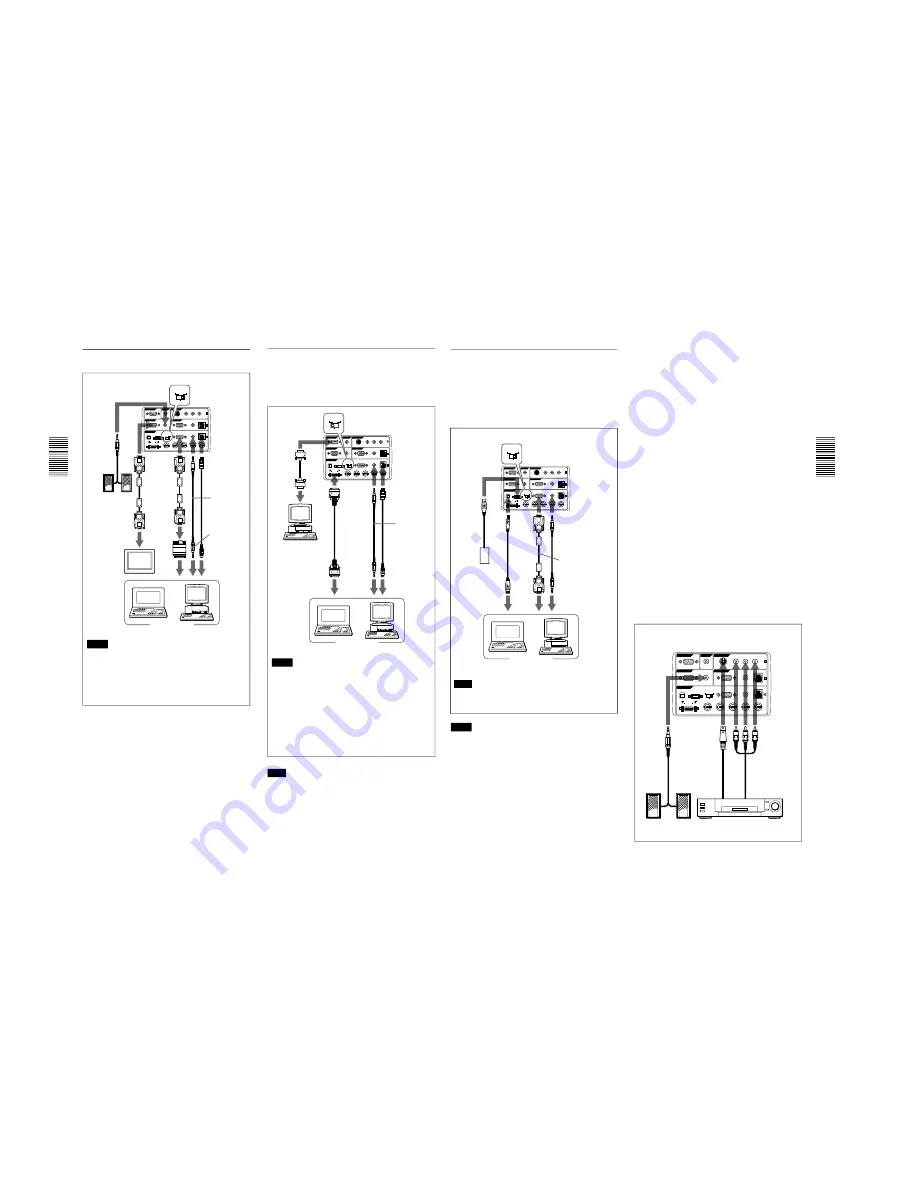
When connecting with a Macintosh
computer
Right side
SIC-S20
Mouse
cable (not
supplied)
to mouse
port
to audio out
to
monitor
out
Connecting
Signal
adapter
(not
supplied)
RS-232C
IN
PLUG IN POWER
OUTPUT
INPUT A
INPUT B
VIDEO IN
CONTROL S
REMOTE
DIGITAL RGB
USB
R/R-Y/PR
B/B-Y/PB SYNC/HD
VD
G/Y
MOUSE
AUDIO
RGB
MOUSE
AUDIO
AUDIO
RGB
MONITOR
S VIDEO
VIDEO
AUDIO
L
R
(MONO)
DIGITAL
RGB
RGB
5BNC
DIGITAL
RGB
RGB
5BNC
Stereo audio
connecting
cable (not
supplied)
Computer
Monitor
Monitor
cable
SMF-410
(not
supplied)
HD D-sub
15-pin
cable
(supplied)
Speaker
Notes
• Set the DIGITAL RGB/5BNC/RGB switch to
RGB (right) when you connect the computer to
the INPUT A connector.
• When you connect with a Macintosh computer,
you need the optional signal adapter.
Right side
Using the DIGITAL RGB (TMDS)
connector
Connect the computer to the DIGITAL RGB (TMDS)
connector on the connector panel.
Note
If you use the DIGITAL RGB (TMDS) connector, the
MONITOR connector will not output image signals.
Notes
• Use the proper mouse cable for your computer.
• You can use a USB mouse. For details, see
“Using USB equipment (e.g., USB mouse)”.
• Set the DIGITAL RGB/5BNC/RGB switch to
DIGITAL RGB (left).
• To connect digital RGB equipment, use the digital
signal cable (SMF-D102 or SMF-D110) (not
supplied). Do not use other cables — noise may
appear on the image.
to INPUT A
or INPUT B
Mouse cable
Stereo audio
connecting
cable (not
supplied)
Digital signal
cable
SMF-D102
(not supplied)
or
SMF-D110
(not supplied)
RS-232C
IN
PLUG IN POWER
OUTPUT
INPUT A
INPUT B
VIDEO IN
CONTROL S
REMOTE
DIGITAL RGB
USB
R/R-Y/PR
B/B-Y/PB SYNC/HD
VD
G/Y
MOUSE
AUDIO
RGB
MOUSE
AUDIO
AUDIO
RGB
MONITOR
S VIDEO
VIDEO
AUDIO
L
R
(MONO)
DIGITAL
RGB
RGB
5BNC
DIGITAL
RGB
RGB
5BNC
to mouse
port
to digital
RGB out
to audio
out
Computer
Computer
Remote
cable
to
RS-232C
port
17
(GB)
Connecting
Using USB equipment (e.g., USB mouse)
Connect the USB equipment to the USB connector on
the connector panel.
You can connect your computer to the projector via
the RGB connector, 5BNC connector or DIGITAL
RGB connector. (The example below uses the RGB
connector.)
Notes
• Your computer may not start correctly when it has
been connected to the USB connector on the
projector via the USB cable. In this case, first
disconnect the USB cable, restart the computer, then
connect the computer to the projector using the USB
cable supplied with the projector.
• The USB connector on this projector will function
only with a computer operated with Windows 98.
• When you connect the mouse to your computer via
the USB connector, do not connect another mouse to
the MOUSE port. The projector automatically
assumes that a USB mouse is connected.
Note
Set the DIGITAL RGB/5BNC/RGB switch to the
suitable position depending on the connection.
RS-232C
IN
PLUG IN POWER
OUTPUT
INPUT A
INPUT B
VIDEO IN
CONTROL S
REMOTE
DIGITAL RGB
USB
R/R-Y/PR
B/B-Y/PB SYNC/HD
VD
G/Y
MOUSE
AUDIO
RGB
MOUSE
AUDIO
AUDIO
RGB
MONITOR
S VIDEO
VIDEO
AUDIO
L
R
(MONO)
DIGITAL
RGB
RGB
5BNC
DIGITAL
RGB
RGB
5BNC
Right side
HD D-sub
15-pin
cable
(supplied)
Stereo audio
connecting
cable (not
supplied)
to
monitor
out
to USB
port
to audio
out
Other USB
equipment
USB
cable A
type-B
type
(sup-
plied)
Computer
USB hub function
If you connect the projector and your computer using
the USB cable for the first time, the following devices
will be recognized.
1
General purpose USB hub
2
USB human interface device (for wireless mouse
function)
3
USB human interface device (for projector control
function)
Any other devices connected to the downstream
connector of a projector are recognized by your
computer.
Connecting with a VCR/15k RGB/
Component Equipment
This section describes how to connect the projector
with a VCR, external active speakers, and 15k RGB/
component equipment.
Also refer to the instruction manuals of the equipment
to be connected.
When making connections, be sure to:
• turn off all equipment before making any
connections.
• use the proper cables for each connection.
• insert the plugs of the cables properly; plugs that are
not fully inserted often generate noise. When pulling
out a cable, be sure to pull it out from the plug, not
the cable itself.
S-Video cable
(not supplied)
Audio/video
cable
(supplied)
Active speakers
to audio/video
outputs
to S video
output
VCR
Right side
RS-232C
IN
PLUG IN POWER
OUTPUT
INPUT A
INPUT B
VIDEO IN
CONTROL S
REMOTE
DIGITAL RGB
USB
R/R-Y/P
R
B/B-Y/P
B
SYNC/HD
VD
G/Y
MOUSE
AUDIO
RGB
MOUSE
AUDIO
AUDIO
RGB
MONITOR
S VIDEO
VIDEO
AUDIO
L
R
(MONO)
DIGITAL
RGB
RGB
5BNC
Содержание RM-PJM610
Страница 153: ...9 20 9 20 A B C D E F G H 1 2 3 4 5 VPL PX20 PX30 ...
Страница 161: ...9 28 9 28 A B C D E F G H 1 2 3 4 5 VPL PX20 PX30 C B SIDE SUFFIX 11 C A SIDE SUFFIX 11 ...
Страница 165: ...9 32 9 32 A B C D E F G H 1 2 3 4 5 VPL PX20 PX30 Y S NF NR Y S NF NR ...
Страница 177: ...Sony Corporation B P Company English 99KZ08111 1 Printed in Japan 1999 11 9 929 667 01 ...


