


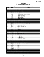


5-3
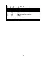
I/O
I
I
–
I
–
–
O
I
I
–
–
I
–
I
I
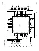
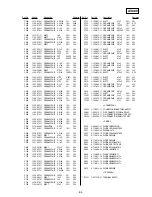
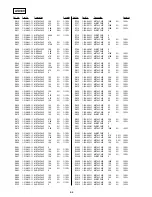
Pin No.
101
102
103
104
105
106
107
108
109
110
111
112
113
114
115
116
Pin Name
IT_CON_TEMP
BS_C/N_DET
AVSS
TU_G_MAX
VREF
AVCC
XL3MUTE
START
SYNCIN
SVREF
TEST2
VDD3
CVIN1
VSS3
FSCIN
TU_ATF
Function
Terminal control signal input
Fixed at “L”
Analog GND
Tuner gain detect signal input
Power supply input (Analog 5V)
Power supply input (Analog 6V)
Not used
Oscillation selection input
Composite video signal input 2
When slice the vertical synchronous signal input slice power
Digital GND
Power supply input (Analog 5V)
Component video signal input 1
Analog GND
Not used
Tuner AFT control
Содержание RDR-HX510
Страница 6: ...MEMO 6 ...
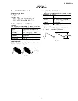
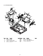
Страница 35: ...2 3 2 3 FRONT PANEL SECTION 2 4 SLIDE DOOR 2 Front panel section 1 Seven dowels 1 Four dowels 2 Slide door ...
Страница 42: ...2 10E MEMO ...
Страница 50: ...RDR HX510 MEMO 3 15 3 16E ...
Страница 82: ...MEMO 5 4E ...