1-6
24
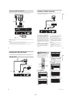
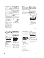
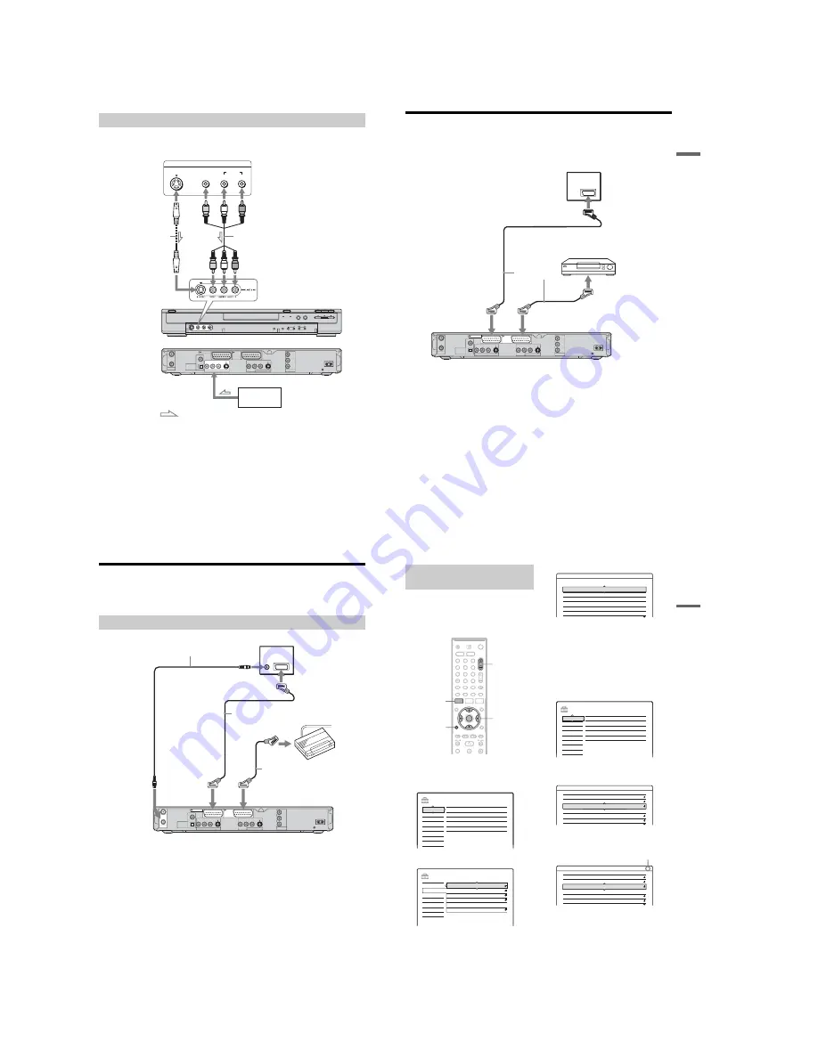
Connect a VCR or similar recording device to the LINE 2 IN or LINE 4 IN jacks of this recorder. If the
equipment has an S-video jack, you can use an S-video cord instead of an audio/video cord.
z
Hint
When the connected equipment outputs only monaural sound, use audio cables that distribute monaural sounds to left/
right channels (not supplied).
b
Notes
• Do not connect the yellow LINE IN (VIDEO) jack when using an S-video cord.
• Do not connect the output jack of this recorder to another equipment’s input jack with the other equipment’s output
jack connected to the input jack of this recorder. Noise (feedback) may result.
• Do not connect more than one type of video cord between the recorder and your TV at the same time.
Connecting to the LINE 2 IN or LINE 4 IN jacks
AERIAL
IN
DIGITAL OUT
COAXIAL
OPTICAL
PCM/DTS/MPEG/
DOLBY DIGITAL
COMPONENT
VIDEO OUT
LINE 2 OUT
VIDEO
S VIDEO
R-AUDIO-L
PB / CB
Y
PR / CR
~
AC IN
OUT
LINE 1 - TV
LINE 3
/DECODER
LINE 4 IN
VIDEO
S VIDEO
R-AUDIO-L
OUTPUT
S VIDEO
AUDIO
L
R
VIDEO
VCR, etc.
Audio/video cord
(not supplied)
S-video cord
(not supplied)
to LINE 2 IN
DVD recorder (front)
: Signal flow
(rear)
to LINE 4 IN
VCR, etc.
25
H
ook
up
s and
Se
tti
n
gs
Connecting to a Satellite or Digital Tuner
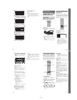
Connect a satellite or digital tuner to this recorder using the LINE 3/DECODER jack. Disconnect the
recorder’s mains lead from the mains when connecting the tuner.
To use the Synchro-Rec function, see below.
If the satellite tuner can output RGB signals
This recorder accepts RGB signals. If the satellite
tuner can output RGB signals, connect the TV
SCART connector on the satellite tuner to the
LINE 3/DECODER jack, and set “Line3 Input” of
“Scart Setting” to “Video/RGB” in “Video” setup
(page 82). Note that this connection and setup
disable the SMARTLINK function. If you want to
use the SMARTLINK function with a compatible
set top box, see the instructions supplied with the
set top box.
If you want to use the Synchro Rec function
This connection is necessary to use the Synchro-
Recording function. See “Recording from
connected equipment with a timer (Synchro Rec)”
on page 49.
Set “Line3 Input” of “Scart Setting” in “Video”
setup (page 82) according to the specifications of
your satellite tuner. See your satellite tuner’s
instructions for more information.
If you are using a B Sky B tuner, be sure to
connect the tuner’s VCR SCART jack to the LINE
3/DECODER jack. Then set “Line3 Input” of
“Scart Setting” according to the specifications of
the VCR SCART jack on your satellite tuner.
b
Notes
• Do not set “Line3 Input” of “Scart Setting” in “Video”
setup to “Decoder.”
• Synchronized Recording does not work with some
tuners. For details, see the tuner’s operating
instructions.
• If you disconnect the recorder’s mains lead, you will
not be able to view the signals from the connected
tuner.
AERIAL
IN
LINE 4 IN
DIGITAL OUT
COAXIAL
OPTICAL
PCM/DTS/MPEG/
DOLBY DIGITAL
COMPONENT
VIDEO OUT
VIDEO
S VIDEO
R-AUDIO-L
PB / CB
Y
PR / CR
~
AC IN
OUT
LINE 2 OUT
VIDEO
S VIDEO
R-AUDIO-L
LINE 3
/DECODER
LINE 1 - TV
TV
to SCART input
SCART cord
(not supplied)
Satellite tuner, etc.
to
i
LINE 1 – TV
to
i
LINE 3/DECODER
DVD recorder
26
Connecting a PAY-TV/Canal Plus Decoder
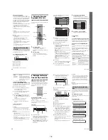
You can watch or record PAY-TV/Canal Plus programmes if you connect a decoder (not supplied) to the
recorder. Disconnect the recorder’s mains lead from the mains when connecting the decoder.
Connecting a decoder
AERIAL
IN
LINE 4 IN
DIGITAL OUT
COAXIAL
OPTICAL
PCM/DTS/MPEG/
DOLBY DIGITAL
COMPONENT
VIDEO OUT
VIDEO
S VIDEO
R-AUDIO-L
PB / CB
Y
PR / CR
~
AC IN
OUT
LINE 2 OUT
VIDEO
S VIDEO
R-AUDIO-L
LINE 3
/DECODER
LINE 1 - TV
TV
Aerial cable
(supplied)
SCART cord
(not supplied)
PAY-TV/Canal Plus
decoder
to AERIAL OUT
to
i
LINE 3/DECODER
DVD recorder
to AERIAL IN
to SCART input
SCART cord (not supplied)
to
i
LINE 1 – TV
27
H
ook
up
s and
Se
tti
n
gs
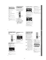
To watch or record PAY-TV/Canal Plus
programmes, set your recorder to receive the
channels using the on-screen display.
In order to set the channels correctly, be sure to
follow all of the steps below.
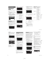
1
Press SYSTEM MENU.
The System Menu appears.
2
Select “SETUP,” and press ENTER.
3
Select “Video,” and press ENTER.
4
Select “Scart Setting,” and press ENTER.
5
Press
M
/
m
to select “Video” or “RGB” for
“Line1 Output,” “Decoder” for “Line3
Input,” and “Video” for “Line3 Output,”
and press ENTER.
The “Video” setup display appears again.
6
Press
O
RETURN to return the cursor to
the left column.
7
Select “Settings,” and press ENTER.
8
Select “Channel Setting,” and press
ENTER.
9
Press PROG +/– to select the desired
programme position.
Setting PAY-TV/Canal Plus
channels
1
2
3
4
6
7
8
9
0
5
SYSTEM
MENU
O
RETURN
PROG +/–
<
/
M
/
m
/
,
,
ENTER
SETUP
Settings
Easy Setup
Channel Setting
Options
Features
Audio
Video
Language
Clock
TV Guide Page
Channel List
SETUP
TV Type :
16 : 9
Video
Settings
Easy Setup
Options
Features
Audio
Video
Line4 Input :
Scart Setting
Progressive Mode :
Component Out :
Pause Mode :
Auto
Off
Auto
Video - Scart Setting
Line1 Output
Line3 Input
Line3 Output
Video
Video/RGB
Video
RGB
S Video
S Video
S Video
S Video
S Video
S Video
Video
Video
Video
Video
Video
Video/RGB
Decoder
Video/RGB
SETUP
Settings
Easy Setup
Channel Setting
Options
Features
Audio
Video
Language
Clock
TV Guide Page
Channel List
Settings - Channel Setting
Prog. 8
System :
BG
2
Audio :
PAY - TV / CANAL+ :
Station Name :
Channel Set :
Normal / CATV :
NICAM
Off
CDE
C
Normal
Settings - Channel Setting
Prog. 6
24
System :
Audio :
PAY - TV / CANAL+ :
Station Name :
Channel Set :
Normal / CATV :
BG
NICAM
Off
PQR
C
Normal
Selected programme position
,
continued
Содержание RDR-HX510
Страница 6: ...MEMO 6 ...
Страница 35: ...2 3 2 3 FRONT PANEL SECTION 2 4 SLIDE DOOR 2 Front panel section 1 Seven dowels 1 Four dowels 2 Slide door ...
Страница 42: ...2 10E MEMO ...
Страница 50: ...RDR HX510 MEMO 3 15 3 16E ...
Страница 82: ...MEMO 5 4E ...

