1-5
20
4
Release
[
/
1
.
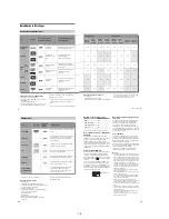
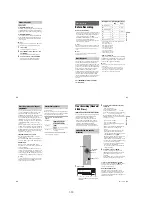
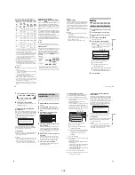
When the TV/DVD switch is set to TV, the
remote performs the following:
* If you use the number buttons to select the TV’s
programme position, press -/-- followed by the
number buttons for two-digit numbers.
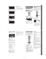
To operate the
t
TV/VIDEO button
(for SCART connections only)
The
t
TV/VIDEO button switches between the
recorder and the last input source selected on the
TV. Point your remote at the recorder when using
this button. The button works even if the TV/DVD
switch is set to DVD.
When you connect the recorder to the TV via the
SCART jacks, the input source for the TV is set to
the recorder automatically when you start
playback. To watch another source, press the
t
TV/VIDEO button to switch the TV’s input
source.
Code numbers of controllable TVs
If more than one code number is listed, try
entering them one at a time until you find the one
that works with your TV.
1
Slide the TV/DVD switch to DVD.
2
Hold down
[
/
1
, and enter the
manufacturer code (see the table below)
for your AV amplifier (receiver) using the
number buttons.
3
Release
[
/
1
.
The
2
(volume) +/– buttons control the AV
amplifier’s volume.
If you want to control the TV’s volume, slide
the TV/DVD switch to TV.
z
Hint
If you want to control the TV’s volume even when the
TV/DVD switch is set to DVD, repeat the steps above
and enter the code number 90 (default).
Buttons
Operations
[
/
1
Turns your TV on or off
2
(volume) +/–
Adjusts the volume of
your TV
PROG +/–
Selects the programme
position on your TV
(wide mode)
Switches to or from the
wide mode of a Sony
wide-screen TV
t
TV/VIDEO
Switches your TV’s
input source
Number buttons
and SET, -/--*
Selects the programme
position on your TV
Manufacturer
Code number
Sony
01 (default)
Aiwa
01 (default)
Grundig
11
Hitachi
23, 24, 72
Loewe
06, 45
Nokia
15, 16, 69, 73
Panasonic
17, 49
Philips
06, 07, 08, 23, 45, 72
Saba
12, 13, 36, 43, 74, 75
Samsung
06, 22, 23, 71, 72
Sanyo
25
Sharp
29
Telefunken
12, 13, 36, 43, 74, 75
Thomson
12, 13, 43, 74, 75
Toshiba
38
LG
06
JVC
33
Controlling the volume of your AV
amplifier (receiver) with the
remote
Manufacturer
Code number
1
2
3
4
6
7
8
9
0
5
TV/DVD
switch
[
/
1
2
+/–
Number buttons
21
H
ook
up
s and
Se
tti
n
gs
Code numbers of controllable AV amplifiers
(receivers)
If more than one code number is listed, try
entering them one at a time until you find the one
that works with your AV amplifier (receiver).
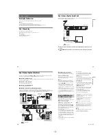
If the supplied remote interferes with your other
Sony DVD recorder or player, set the command
mode number for this recorder and the supplied
remote to one that differs from the other Sony
DVD recorder or player.
The default command mode setting for this
recorder and the supplied remote is DVD3.
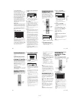
1
Press SYSTEM MENU.
The System Menu appears.
2
Select “SETUP,” and press ENTER.
3
Select “Options,” and press ENTER.
4
Select “Command Mode,” and press
ENTER.
5
Select the Command mode (DVD1, DVD2,
or DVD3), and press ENTER.
6
Slide the COMMAND MODE switch on the
remote so it matches the mode you
selected above.
To return to the previous step
Press
O
RETURN.
Manufacturer
Code number
Sony
78, 79, 80, 91
Denon
84, 85, 86
Kenwood
92, 93
Onkyo
81, 82, 83
Pioneer
99
Sansui
87
Technics
97, 98
Yamaha
94, 95, 96
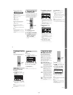
If you have a Sony DVD player or
more than one Sony DVD recorder
1
2
3
4
6
7
8
9
0
5
SYSTEM
MENU
M
/
m
,
ENTER
COMMAND
MODE
switch
O
RETURN
Check that the command mode switch on the
remote is set to the default setting of DVD3
before you try to change the command mode for
the recorder. If the command mode for the remote
is changed to DVD1 or DVD2, you may be
unable to operate this recorder.
SETUP
Settings
Easy Setup
Channel Setting
Options
Features
Audio
Video
Language
Clock
TV Guide Page
Channel List
SETUP
Format DVD-RW :
VR
Settings
Options
Features
Audio
Video
Easy Setup
Command Mode :
Factory Setup
Auto Display :
Power Save :
Dimmer :
DVD Bilingual Rec. :
HDD Bilingual Rec. :
DVD3
On
Off
Normal
Main
Main
SETUP
Format DVD-RW :
VR
Settings
Options
Features
Audio
Video
Easy Setup
Command Mode :
Factory Setup
Auto Display :
Power Save :
Dimmer :
DVD Bilingual Rec. :
HDD Bilingual Rec. :
DVD3
On
Off
Normal
Main
Main
DVD1
DVD3
DVD2
22
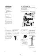
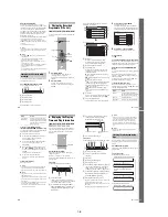
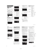
Step 7: Easy Setup
Make the basic adjustments by following the
on-screen instructions in “Easy Setup.”
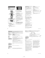
1
Turn on the recorder and switch the input
selector on your TV so that the signal from
the recorder appears on your TV screen.
The message about the initial settings appears.
• If this message does not appear, select “Easy
Setup” from “SETUP” in the System Menu
to run “Easy Setup” function (“Settings and
Adjustments” on page 76).
2
Press ENTER.
Follow the on-screen instructions to make the
following settings.
OSD
Select the language for the on-screen displays.
Tuner System
Select your country or language.
The programme position order will be set
according to the country you set.
To set the programme positions manually, see
page 76.
• If you live in a French speaking country that
is not listed on the display, select “ELSE.”
Clock
The recorder will automatically search for a
clock signal. If a clock signal cannot be found,
set the clock manually using
<
/
M
/
m
/
,
, and
press ENTER.
TV Type
If you have a wide-screen TV, select “16:9.”
If you have a standard TV, select either “4:3
Letter Box” (shrink to fit) or “4:3 Pan Scan”
(stretch to fit). This will determine how
“wide-screen” images are displayed on your
TV.
Component Out
If you are using the COMPONENT VIDEO
OUT jack, select “On.”
Line3 Input
If you will connect a decoder to the LINE 3/
DECODER jack, select “Yes.”
Line1 Output
To output video signals, select “Video.”
To output S video signals, select “S Video.”
To output RGB signals, select “RGB.”
Select “Video” to enjoy the SMARTLINK
features.
• If you set “Component Out” to “On,” you
cannot select “RGB.”
If you set “Line3 Input” to “Yes,” you
cannot select “S Video.”
Audio Connection
If you connected an AV amplifier (receiver)
using either a digital optical or coaxial cord,
select “Yes: DIGITAL OUT” and set the
digital output signal (page 84).
3
Press ENTER when “Finish” appears.
“Easy Setup” is finished.
To return to the previous step
Press
O
RETURN.
z
Hints
• If your AV amplifier (receiver) has an MPEG audio
decoder, set “MPEG” to “MPEG” (page 84).
• If you want to run “Easy Setup” again, select “Easy
Setup” from “SETUP” in the System Menu (page 88).
1
2
3
4
6
7
8
9
0
5
[
/
1
<
/
M
/
m
/
,
,
ENTER
O
RETURN
PROG +/–
23
H
ook
up
s and
Se
tti
n
gs
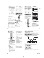
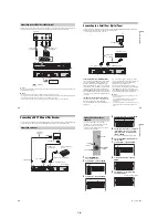
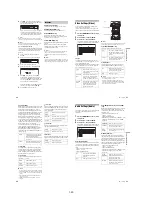
Connecting a VCR or Similar Device
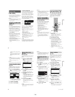
After disconnecting the recorder’s mains lead from the mains, connect a VCR or similar recording device
to the LINE IN jacks of this recorder.
See also the instruction manual supplied with the connected equipment.
To record on this recorder, see “Recording from connected equipment without a timer” on page 50.
Connect a VCR or similar recording device to the LINE 3/DECODER jack of this recorder.
b
Notes
• Pictures containing copy protection signals that prohibit any copying cannot be recorded.
• If you pass the recorder signals via the VCR, you may not receive a clear image on your TV screen.
Be sure to connect your VCR to the DVD recorder and your TV in the order shown below. To watch video tapes,
watch the tapes through a second line input on your TV.
• The SMARTLINK features are not available for devices connected via the DVD recorder’s LINE 3/DECODER jack.
• When you record to a VCR from this DVD recorder, do not switch the input source to TV by pressing the
t
TV/
VIDEO button on the remote.
• If you disconnect the recorder’s mains lead, you will not be able to view the signals from the connected VCR.
Connecting to the LINE 3/DECODER jack
AERIAL
IN
LINE 4 IN
DIGITAL OUT
COAXIAL
OPTICAL
PCM/DTS/MPEG/
DOLBY DIGITAL
COMPONENT
VIDEO OUT
VIDEO
S VIDEO
R-AUDIO-L
PB / CB
Y
PR / CR
~
AC IN
OUT
LINE 2 OUT
VIDEO
S VIDEO
R-AUDIO-L
LINE 3
/DECODER
LINE 1 - TV
TV
DVD recorder
to
i
LINE 1 – TV
VCR
to
i
LINE 3/DECODER
SCART cord (not supplied)
to SCART input
VCR
DVD recorder
TV
VCR
DVD recorder
TV
Line input 1
Line input 2
,
continued
Содержание RDR-HX510
Страница 6: ...MEMO 6 ...
Страница 35: ...2 3 2 3 FRONT PANEL SECTION 2 4 SLIDE DOOR 2 Front panel section 1 Seven dowels 1 Four dowels 2 Slide door ...
Страница 42: ...2 10E MEMO ...
Страница 50: ...RDR HX510 MEMO 3 15 3 16E ...
Страница 82: ...MEMO 5 4E ...

