PRS-T1
11
14. Write VCOM
In this mode, the VCOM voltage can be rewritten.
The VCOM voltage for INK INDICATOR 6inch ELEMENT is
individually different.
Therefor, when replacing the complete MAIN board or CHASSIS
ASSY (including INK INDICATOR 6inch ELEMENT) you need
to rewrite the VCOM voltage.
Procedure:
1. The VCOM voltage con
fi
rm method is different according to
replaced parts.
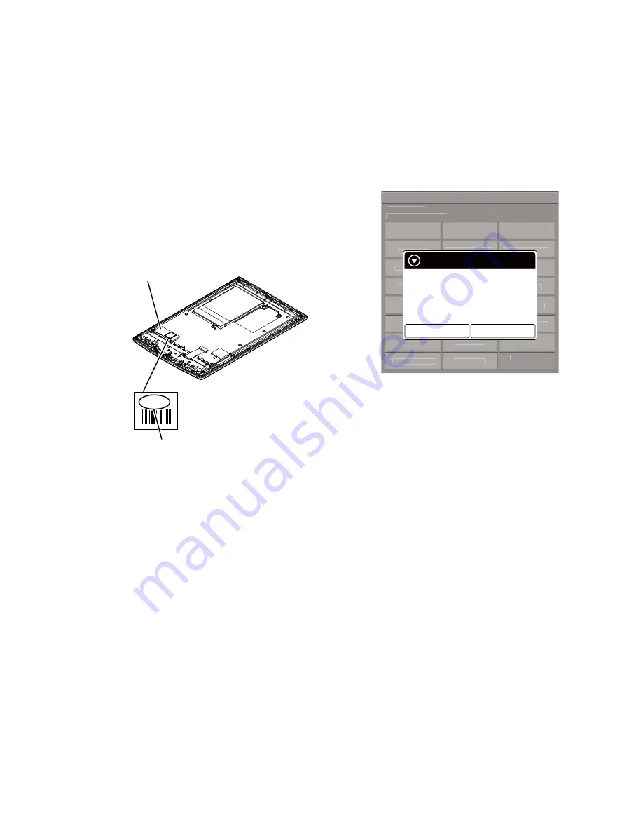
When the complete MAIN board is replaced:
Disassemble this unit until the VCOM voltage is seen (Refer to
“2. DISASSEMBLY” (pages 3 to 7)), and con
fi
rm the VCOM
voltage referring to the
fi
gure below. Record the con
fi
rmed the
VCOM voltage by taking the memo etc..
Flexible board of INK
INDICATOR 6inch ELEMENT
VCOM voltage
-2.03
When the CHASSIS ASSY (including INK INDICATOR
6inch ELEMENT) is replaced:
Con
fi
rm the VCOM voltage described on the label of new
CHASSIS ASSY (including INK INDICATOR 6inch ELE-
MENT). Record the con
fi
rmed the VCOM voltage by taking
the memo etc..
2. Replace complete MAIN board or CHASSIS ASSY (including
INK INDICATOR 6inch ELEMENT) for new parts, and as-
semble this unit.
3. Make the text
fi
le on PC, and write the VCOM voltage con-
fi
rmed in step 1.
Note 1:
The VCOM voltage is described by the unit of mV that omits
minus (Example: Write “2030” when it is printed on the label as
“–2.03 V”).
4. Press the [
1
] key to turn the power on.
5. Con
fi
rm the HOME menu was completely displayed, and con-
nect this unit to PC by the USB cable (MICRO B).
6. Con
fi
rm the USB connection screen displayed, and touch the
“Data Transfer Mode”.
7. Con
fi
rm the “READER” drive of this unit is recognized.
8. Make the following folder under the “READER” drive of this
unit.
/testmode/data/
9. Copy the text
fi
le made in step 3 to the “data” folder made in
step 8. Then, change the
fi
le name to “Vcom.dt”.
10. Copy the
fi
le for the test mode from PC to directly under the
“READER” drive of this unit.
Note 2:
When the
fi
le for the test mode already exists directly under the
“READER” drive of this unit, the
fi
le for the test mode need not
be newly copied.
11. Remove this unit and USB cable (MICRO B) from PC.
12. Enter the test mode (Refer to “HOW TO ENTER THE TEST
MODE” (page 8)).
13. Touch the “Write VCOM” in the test mode menu, and con
fi
rm
current (unrenewed) VCOM voltage is displayed (Example:
-1854 mV in the
fi
gure below).
@Test Mode
Version: X.X.X
Target storage: Internal
Test Panal
Update Waveform
IR-LED Level
Drawing with
Points
Reset Device Lock
Check 3G Module
TP Coordinate
Power Off
Check User
History
Test All Key
Log Extact 1
Switch ADB
Test Battery Life
Check
Temperature
Fake MoAkey
Version
Confirmation
Write VCOM
Reboot (Normal)
Check Battery
WWAN ON
Reboot (Recovery)
Factory Initialize
WWAN OFF
Log Extact 2
(Flush)
Write VCOM
Status: 1854mV
Whould you like to write?
New value: 2030mV
Yes
No
(Example of displaying current
(unrenewed) VCOM voltage)
14. Touch the “Yes”, it starts rewriting the VCOM voltage.
15. Con
fi
rm the VCOM voltage has been updated.
15. WWAN ON
This mode is not used in servicing.
16. WWAN OFF
This mode is not used in servicing.
17. IR-LED Level
This mode is not used in servicing.
18. Check 3G Module
This mode is not used in servicing.
19. Check User History
This mode is not used in servicing.
20. Switch ADB
This mode is not used in servicing.
21. Fake MoAkey
This mode is not used in servicing.
22. Reboot (Normal)
This mode is not used in servicing.
23. Reboot (Recovery)
This mode is not used in servicing.
24. Log Extact 2 (Flush)
This mode is not used in servicing.


