


38
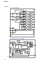
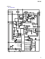
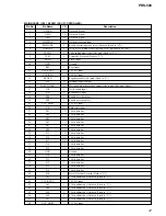
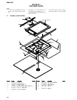
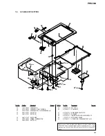
PRS-500
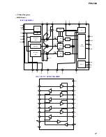
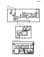
MAIN BOARD IC801 HD64338002A21FPV (SUB CPU)
Pin No.
Pin Name
I/O
Description
1
BATT-DC
I
AC adapter DC input
2
X1
I
32.768kHz clock input
3
X2
O
32.768kHz clock output
4
VSS
—
Ground
5
OSC2
O
4.9152MHz clock output
6
OSC1
I
4.9152MHz clock input
7
TEST
I
Test terminal (Short GND)
8
RESET
I
Reset input
9
N.C.
I
Not used (Fixed to “H”)
10
N.C.
I
Not used (Fixed to “H”)
11
P33
Not used (Fixed to “H”)
12
P34
Not used (Fixed to “H”)
13
P35
Not used (Fixed to “H”)
14
STAT1
I
Charge monitor input1
15
STAT2
I
Charge monitor input2
16
VCC
—
2.9V DC input
17
V1
—
Not used (Fixed to “H”)
18
V2
—
Not used (Fixed to “H”)
19
V3
—
Not used (Fixed to “H”)
20
PWRON
O
Main power on signal output
21
AD_ON
O
A/D input control signal output
22
POR
I/O
Power on reset input/output
23
M_RESET
I/O
Reset input/output
24
USBON
O
USB charge control output
25
KEY_OUT7
O
Key scan output
26
KEY_OUT6
O
Key scan output (Not used (Open))
27
KEY_OUT5
O
Key scan output (Not used (Open))
28
KEY_OUT4
O
Key scan output
29
KEY_OUT3
O
Key scan output
30
KEY_OUT2
O
Key scan output
31
KEY_OUT1
O
Key scan output (Not used (Open))
32
KEY_OUT0
O
Key scan output (Not used (Open))
33
KEY_in7
I
Key scan input
34
KEY_IN6
I
Key scan input
35
KEY_IN5
I
Key scan input
36
KEY_IN4
I
Key scan input
37
KEY_IN3
I
Key scan input
38
KEY_IN2
I
Key scan input
39
KEY_IN1
I
Key scan input
40
KEY_IN0
I
Key scan input
41
KEY-INT
I
Key scan interrupt input
42
CTS
I
CTS(UART) input
43
USBDET
I
USB cable insert detect signal
44
LOW-BATT-LI
I
Lithium battery low detect input
45
N.C.
I
Not used (Fixed to “L”)
46
USBCHG
I
USB charge permit input
47
DCDET
I
AC adapter DC detect input
48
STBY_SW
I
Standby switch input


