38
NW-A1000
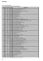
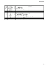
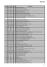
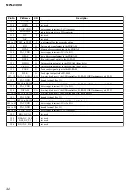
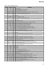
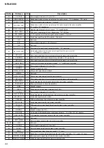
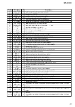
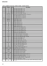
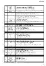
IC5001 S1R72003BOOA100 (USB CONTROLLER)
Pin No.
Pin Name
I/O
Description
1
R1
I/O
Internal operation setting terminal
2
N.C.
-
Not used
3
AVSS
-
Ground terminal (analog system)
4
AVDD
-
Power supply terminal (+3.3V) (analog system)
5
AVSS
-
Ground terminal (analog system)
6
AVDD
-
Power supply terminal (+3.3V) (analog system)
7
AVSS
-
Ground terminal (analog system)
8
DP
I/O
USB data (+) input/output terminal
9
AVSS
-
Ground terminal (analog system)
10
DM
I/O
USB data (-) input/output terminal
11
AVSS
-
Ground terminal (analog system)
12
AVDD
-
Power supply terminal (+3.3V) (analog system)
13
TSTEN
I
Input terminal for the test mode setting
14
VBUS
I
USB bus detection signal input terminal
15
XRESET
I
Reset signal input from the power control "L": reset
16
XSLEEP
I
Sleep signal input from the PLD "L": sleep mode
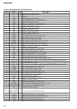
17 to 24
CA0 to CA7
I
Address signal input from the main system controller
25
VSS
-
Ground terminal (logic system)
26
VDD
-
Power supply terminal (+3.3V) (logic system)
27
XCS
I
Chip select signal input terminal Not used
28
XRD
I
Read signal input from the main system controller
29
XWAIT
O
Wait signal output to the main system controller
30
XWR
I
Write signal input from the main system controller
31
XINT
O
Interrupt request signal output to the main system controller
32 to 35
CD0 to CD3
I/O
Two-way data bus with the main system controller, SD-RAM, NOR flash memory and PLD
36
VSS
-
Ground terminal (logic system)
37 to 40
CD4 to CD7
I/O
Two-way data bus with the main system controller, SD-RAM, NOR flash memory and PLD
41
VDD
-
Power supply terminal (+3.3V) (logic system)
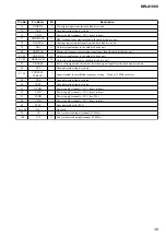
42
ATPGEN
I
Input terminal for the test mode setting
43
SCANEN
I
Input terminal for the test mode setting
44, 45
TPORT0, TPORT1
I/O
Input/output terminal for the test mode setting
46, 47
TIN0, TIN1
I
Input terminal for the test mode setting
48
VSS
-
Ground terminal (logic system)
49
OSCOUT
O
Clock signal output terminal Not used
50
VSS
-
Ground terminal (logic system)
51
VDD
-
Power supply terminal (+3.3V) (logic system)
52
XHRESET
O
Reset signal output to the hard disk drive unit "L": reset
53 to 60
HDD4 to HDD11
I/O
Two-way data bus with the hard disk drive unit
61
VSS
-
Ground terminal (logic system)
62 to 69
HDD0 to HDD3,
HDD12 to HDD15
I/O
Two-way data bus with the hard disk drive unit
70
VDD
-
Power supply terminal (+3.3V) (logic system)
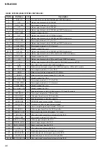
71
HDMARQ
I
DMA request signal input from the hard disk drive unit
72
XHIOW
O
Write signal output to the hard disk drive unit
73
XHIOR
O
Read signal output to the hard disk drive unit

