- 24 -
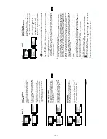
1.
Program the Remote Commander for operation in Service Mode.
[ See Page 22 ] and enter into the ‘Geometry’ service menu.
2.
Select and adjust each item in order to obtain the optimum image.
Deflection System Adjustment
V SIZE
V LIN
AFC BOW
V POSITION
H POSITION
H SIZE
PIN AMP
TRAPEZIUM
UP CORNER PIN
AFC ANGLE
LO CORNER PIN
Y
R
T
E
M
O
E
G
H
T
L
B
A
E
D
O
M
L
B
A
L
B
A
P
E
Z
I
S
V
N
O
I
T
I
S
O
P
V
P
M
O
C
V
N
I
L
V
N
O
I
T
C
E
R
R
O
C
S
E
Z
I
S
H
P
M
A
N
I
P
N
I
P
R
E
N
R
O
C
P
U
N
I
P
M
N
I
P
R
E
N
R
O
C
O
L
M
U
I
Z
E
P
A
R
T
N
O
I
T
I
S
O
P
H
W
O
B
C
F
A
E
L
G
N
A
C
F
A
K
L
B
T
F
E
L
K
L
B
T
H
G
I
R
T
C
E
P
S
A
V
1
M
I
T
B
K
A
2
M
I
T
B
K
A
R
K
I
G
N
H
G
N
V
)
3
,
0
(
)
3
,
0
(
)
5
1
,
0
(
)
3
6
,
0
(
)
3
6
,
0
(
)
3
,
0
(
)
5
1
,
0
(
)
5
1
,
0
(
)
3
6
,
0
(
)
3
6
,
0
(
)
3
6
,
0
(
)
3
,
0
(
)
3
6
,
0
(
)
5
1
,
0
(
)
3
6
,
0
(
)
5
1
,
0
(
)
5
1
,
0
(
)
3
6
,
0
(
)
3
6
,
0
(
)
3
6
,
0
(
)
3
,
0
(
)
1
,
0
(
1
0
0
0
0
5
1
5
3
3
3
1
7
7
4
4
2
3
9
2
2
9
2
2
0
4
8
9
4
3
7
1
7
4
2
0
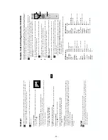
Test Mode 2 is available by rogramming the Remote Commander for
operation in Service Mode [ As shown on Page 22 ] then pressing the
‘VIDEO’ button twice, OSD ‘TT’ appears. The functions described
below are available by selecting the two numbers. To release the ‘Test
mode 2’, press 00, 10, 20 ... twice or switch the TV set into Stand-by
mode. In ‘TT Menu’ mode, it is possible to remove the Menu from
the screen by pressing the Speaker Off button once. Pressing the
Speaker OFF button a second time will cause the Menu to reappear.
The function is kept even when the menu is not displayed on
screen !!.
4-2. TEST MODE 2:
7
2
R
K
E
D
A
n
o
i
t
a
n
i
t
s
e
D
8
2
R
K
E
D
A
n
o
i
t
a
n
i
t
s
e
D
1
3
e
l
b
a
s
i
D
/
e
l
b
a
n
E
f
f
o
t
u
h
S
o
t
u
A
6
3
t
s
e
t
N
O
/
F
F
O
)
M
V
(
n
o
i
t
a
l
u
d
o
M
y
t
i
c
o
l
e
V
1
4
M
V
N
e
s
il
a
i
t
i
n
i
-
e
R
3
4
d
n
u
o
s
A
l
a
u
D
t
c
e
l
e
S
4
4
d
n
u
o
s
B
l
a
u
D
t
c
e
l
e
S
5
4
d
n
u
o
s
o
n
o
M
t
c
e
l
e
S
6
4
d
n
u
o
s
o
e
r
e
t
S
t
c
e
l
e
S
8
4
n
i
g
r
i
v
n
o
n
s
a
M
V
N
t
e
S
9
4
n
i
g
r
i
v
s
a
M
V
N
t
e
S
3
5
e
l
b
a
s
i
D
/
e
l
b
a
n
E
n
o
i
t
a
l
u
d
o
m
r
e
v
O
M
F
5
5
)
S
P
L
A
/
Y
N
O
S
(
n
o
i
t
c
e
l
e
s
r
e
n
u
T
9
5
s
t
r
a
c
S
2
r
o
P
I
P
+
s
t
r
a
c
S
3
l
e
d
o
M
t
c
e
l
e
S
8
6
)
m
e
l
b
o
r
p
N
(
e
r
u
s
a
e
m
r
e
t
n
u
o
c
6
2
X
e
l
b
a
s
i
D
/
e
l
b
a
n
E
3
7
)
4
7
.
6
/
5
.
6
(
m
e
t
s
y
s
2
K
/
D
n
o
t
i
e
w
Z
e
l
b
a
n
E
4
7
)
4
7
.
5
/
5
.
6
(
m
e
t
s
y
s
3
K
/
D
n
o
t
i
e
w
Z
e
l
b
a
n
E
8
7
t
h
g
i
r
ll
u
f
e
c
n
a
l
a
B
9
7
t
f
e
l
ll
u
f
e
c
n
a
l
a
B
7
8
t
s
e
t
s
y
e
k
l
a
c
o
L
9
9
u
n
e
m
e
m
i
T
g
n
i
k
r
o
W
d
n
a
r
o
r
r
E
y
a
l
p
s
i
D
0
0
f
f
o
e
d
o
m
'
T
T
'
1
0
m
u
m
i
x
a
m
e
r
u
t
c
i
P
2
0
m
u
m
i
n
i
m
e
r
u
t
c
i
P
3
0
%
5
3
o
t
e
m
u
l
o
V
e
n
o
h
p
d
a
e
h
/
r
e
k
a
e
p
s
t
e
S
4
0
%
0
5
o
t
e
m
u
l
o
V
e
n
o
h
p
d
a
e
h
/
r
e
k
a
e
p
s
t
e
S
5
0
%
5
6
o
t
e
m
u
l
o
V
e
n
o
h
p
d
a
e
h
/
r
e
k
a
e
p
s
t
e
S
6
0
%
0
8
o
t
e
m
u
l
o
V
e
n
o
h
p
d
a
e
h
/
r
e
k
a
e
p
s
t
e
S
7
0
e
d
o
m
g
n
i
e
g
A
8
0
n
o
i
t
i
d
n
o
C
g
n
i
p
p
i
h
S
1
1
t
n
e
m
t
s
u
j
d
a
e
r
u
t
c
i
p
b
u
S
2
1
t
n
e
m
t
s
u
j
d
a
r
u
o
l
o
c
b
u
S
3
1
t
n
e
m
t
s
u
j
d
a
s
s
e
n
t
h
g
i
r
B
b
u
S
4
1
t
n
e
m
t
s
u
j
d
a
n
o
i
t
i
s
o
P
H
t
x
e
T
5
1
t
s
e
T
li
o
C
n
o
i
t
a
t
o
R
6
1
%
0
5
l
e
v
e
l
e
r
u
t
c
i
P
9
1
e
l
b
a
s
i
D
/
e
l
b
a
n
E
e
d
o
M
y
r
o
t
c
a
F
1
2
R
K
E
D
A
n
o
i
t
a
n
i
t
s
e
D
2
2
L
B
n
o
i
t
a
n
i
t
s
e
D
3
2
R
K
E
D
A
n
o
i
t
a
n
i
t
s
e
D
4
2
U
n
o
i
t
a
n
i
t
s
e
D
5
2
R
K
E
D
A
n
o
i
t
a
n
i
t
s
e
D
6
2
L
B
n
o
i
t
a
n
i
t
s
e
D
Содержание KV-28LS60B
Страница 29: ... 29 29 A Schematic Video Audio Processors Audio Output Vertical Deflection page 1 2 ...
Страница 31: ...A B C D E F G H I J K L M N 1 2 3 4 5 6 7 8 9 10 11 31 A Printed Wiring Board Conductor side A ...
Страница 32: ...A B C D E F G H I J K L M N 1 2 3 4 5 6 7 8 9 10 11 32 A Printed Wiring Board Conductor side B ...
Страница 37: ...A B C D E F G H I J K L M N 1 2 3 4 5 6 7 8 9 10 11 37 G Board Schematic Diagram Power Supply ...
Страница 38: ...A B C D E F G H I J K L M N 1 2 3 4 5 6 7 8 9 10 11 38 C Board Schematic Diagram R G B Out ...
Страница 40: ...A B C D E F G H I J K L M N 1 2 3 4 5 6 7 8 9 10 11 40 M Board Schematic Diagram Micro Processor ...
Страница 42: ...A B C D E F G H I J K L M N 1 2 3 4 5 6 7 8 9 10 11 42 D Board Schematic Diagram Deflection ...

