Ad
minis
tra
ting t
he Camer
a
Setting the Alarm Buffer — Alarm buffer setting Page / Communicating Data via Serial Port — Serial setting Page
39
Setting the Alarm Buffer
— Alarm buffer setting Page
When you click
Alarm buffer
on the Administrator
menu, the Alarm buffer Setting page appears.
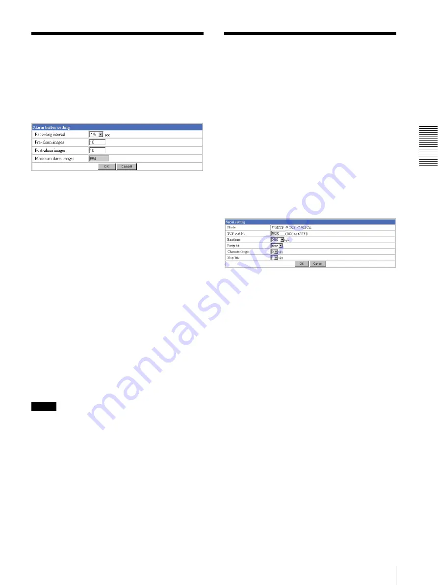
Use this page to set up for the alarm buffer used in the
FTP client function (see page 27) and the Image
memory function (see page 35).
Recording interval
Select the interval (in seconds) at which you want to
record an image in the alarm buffer.
You can select from among the following intervals:
SNC-Z20N:
1/30
,
1/15
,
1/10
,
1/5
,
1/2
,
1
,
2
,
3
,
4
,
5
,
6
,
7
,
8
,
9
,
10
(seconds)
SNC-Z20P:
1/25
,
1/12
,
1/8
,
1/5
,
1/2
,
1
,
2
,
3
,
4
,
5
,
6
,
7
,
8
,
9
,
10
(seconds)
Pre-alarm images
Type the number of images to be recorded before
detecting an alarm (Pre-alarm).
Post-alarm images
Type the number of images to be recorded after
detecting an alarm (Post-alarm).
Maximum alarm images
Displays the maximum number of images that can be
recorded in the alarm buffer with the current image size
and image quality.
Note
The number of Maximum alarm images differs
depending on the Image size and Image quality settings
on the Camera setting page.
Check the Maximum alarm images setting and set so
that the total number of Pre-alarm images and Post-
alarm images does not exceed the Maximum alarm
images.
If you set both Pre-alarm images and Post-alarm images
to
0
, only one image is recorded at the moment when an
alarm is detected.
OK/Cancel
See “Buttons common to every setting page” on page
14.
Communicating Data via
Serial Port
— Serial setting Page
When you click
Serial
on the Administrator menu, the
Serial setting page appears.
Use this page to set up for the date communication via
the serial interface. You can input data from a computer
via the network to the camera, and output it to an
external serial interface for controlling a peripheral
device, or, vice versa, input data from a peripheral
device to the camera via the external serial interface and
output it to the computer via the network.
Perform the setting to match the peripheral device you
connect to the camera.
The external serial interface of this camera conforms to
RS232C standards.
Mode
Select the port through which you send and receive data
via the network:
HTTP
(HTTP Generic Driver) or
TCP
(TCP Generic Driver), or select if the camera is
controlled using the VISCA protocol.
HTTP:
When you select
HTTP
, you can realize data
communication by creating an HTML program with
CGI commands embedded in the computer.
For the CGI commands, consult your authorized
Sony dealer.
TCP:
When you select
TCP
, specify the TCP port
number on the TCP Port No. menu, and you can send
and receive data that is input to or output from the
external serial communication port. You can check
the connection to the camera using a DOS command
“telnet [host name] [assigned port number]”.
VISCA:
When you select
VISCA
, you can control the
camera using the VISCA protocol.
For the command list of the VISCA protocol, consult
your authorized Sony dealer.


