background image

42 

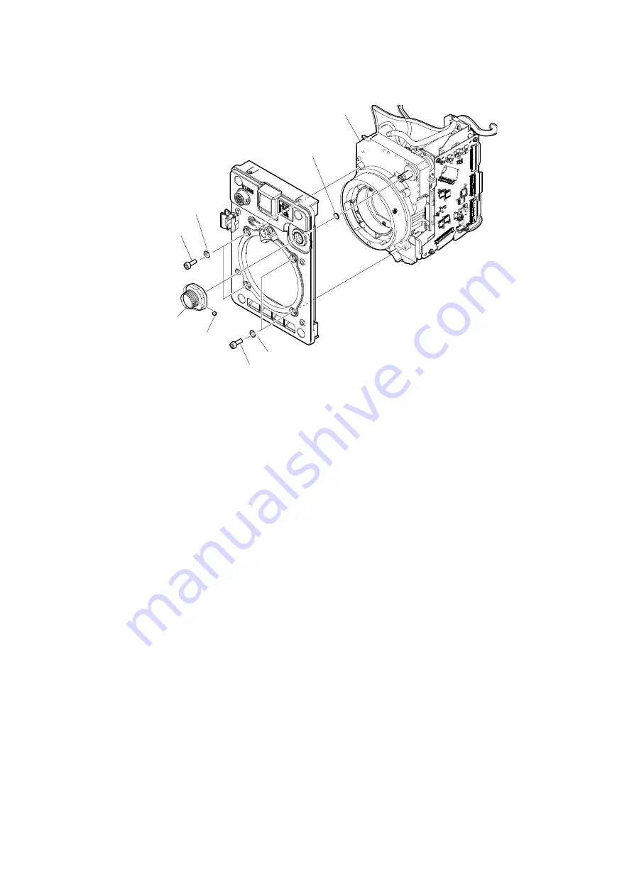
3.  Remove the set screw, and then remove the filter knob. 
4.  Remove the four bolts (M3 x 8) and the four spring washers, and then remove the CMOS block assembly. 
5.  Remove the filter sheet. 


CMOS block assembly

Filter sheet

Spring washers

Spring washers

Set screw

Filter knob

M3 x 8
(tightening torque: 1.1 ± 0.05 N·m)

M3 x 8
(tightening torque: 1.1 ± 0.05 N·m)

Содержание HDC-P31

Страница 1: ... for the purpose of sales installation configuration and use of Sony products Using this information for any purpose other than the purpose described foregoing is forbidden 2 Do not copy replicate reproduce alter translate transmit sell lease or distribute this information in whole or in part without the prior written permission of the author Revision of Information This information may be changed...

Страница 2: ...ischen Schlages Feuergefahr und Verletzungen zu vermeiden sind bei Wartungsarbeiten strikt die Angaben in der Anleitung zu befolgen Andere als die angegeben Wartungsarbeiten dürfen nur von Personen ausgeführt werden die eine spezielle Befähigung dazu besitzen AVERTISSEMENT Ce manual est destiné uniquement aux personnes compétentes en charge de l entretien Afin de réduire les risques de décharge él...

Страница 3: ...egion und des jeweiligen Landes befolgen 注意 指定以外の電池に交換すると 破裂する危険があり ます 必ず指定の電池に交換してください 使用済みの電池は 国または地域の法令に従って 処理してください FÖRSIKTIGHET Fara för explosion vid felaktigt placerat batteri Byt endast mot samma eller likvärdig typ av batteri enligt tillverkarens rekommendationer När du kasserar batteriet ska du följa rådande lagar för regionen eller landet PAS PÅ Fare for eksplosion hvis batteriet ikke u...

Страница 4: ... Maintenance and Inspection 24 2 1 Recommended Replacement Parts 24 2 2 Cleaning the Air Vents 25 2 3 Replacing Lithium Battery 26 2 3 1 Note on Replacement of Lithium Battery 26 2 3 2 Replacing Lithium Battery 26 Section 3 Diagnostics 27 3 1 Device Check 27 3 1 1 BOARD STATUS DIAGNOSIS Menu 27 Section 4 Replacement of Main Parts 28 4 1 Precautions before Work 28 4 1 1 Tightening Torque 28 4 2 Loc...

Страница 5: ...nt 94 5 4 12 File Store 94 5 5 ND Offset Adjustment 95 5 5 1 White Balance Correction 95 5 6 RPN Compensation 97 5 6 1 Automatic Compensation APR 98 5 6 2 Manual RPN Compensation Adjustment 99 5 6 3 Procedures to be Taken when the RPN Compensation Fails 100 5 6 4 Performing Automatic RPN Detection Effectively 101 5 7 Reference Signal System Adjustment 102 5 7 1 27 MHz VCO Free Running Adjustment 1...

Страница 6: ...9 2 1 DPR 393 Board 134 9 2 2 VIF 77 Board 135 9 3 System Control System 135 9 3 1 AT 195 Board 135 9 3 2 SY 471 Board 135 9 4 Interface Boards 136 9 4 1 SW 1753 Board 136 9 4 2 CN 4064 Board 136 9 4 3 CN 4065 Board 136 9 4 4 CN 4066 Board 136 9 4 5 LE 426 Board 136 9 4 6 NET 49 Board 136 9 4 7 MB 1259 Board 136 9 5 Power Supply System 137 9 5 1 MB 1259 Board 137 Section 10 Spare Parts 138 10 1 No...

Страница 7: ...placement and updating the software are required contact your local Sony Sales Office Service Center ROM Peripheral Equipment Board Name Ref No ROM Version CNU 700 AT 89 board or AT 89A board IC4 IC5 Ver 3 43 and higher Software Peripheral Equipment Board Name Software Version RCP 1000 1001 MPU 152 board Ver 2 50 and higher RCP 1500 1501 1530 MPU 153 board Ver 3 20 and higher RCP 3100 AT 195B boar...

Страница 8: ... M4 screw screw depth 5 mm or less The optional V shoe Sony part number A 8279 993 D can be attached by this screw When attaching it use the four alok K4 x 8 screws Sony part number 3 729 072 02 For details on how to purchase the parts contact your local Sony Sales Office Service Center C M4 screw screw depth 6 mm or less D M2 6 screw screw depth 5 mm or less E M3 screw screw depth 7 mm or less Th...

Страница 9: ...2 HDC P50 BNC type 12G SDI signal SMPTE ST2082 1 compliant 0 8 Vp p 75 Ω 11 88 Gbps 11 8681 Gbps serial 3G SDI signal SMPTE 424M 425M B compliant 0 8 Vp p 75 Ω 2 97 Gbps 2 9679 Gbps serial or HD SDI signal SMPTE 292M 372M BTA S004 compliant 0 8 Vp p 75 Ω 1 485 Gbps 1 4835 Gbps serial 1 3 9 6 4 8 10 5 2 7 1 9 6 8 10 4 5 2 7 ...

Страница 10: ...bps 2 9679 Gbps serial or HD SDI signal SMPTE 292M 372M BTA S004 compliant 0 8 Vp p 75 Ω 1 485 Gbps 1 4835 Gbps serial 4 SDI MONI BNC type HD SDI signal SMPTE 292M 372M BTA S004 compliant 0 8 Vp p 75 Ω 1 485 Gbps 1 4835 Gbps serial 5 REMOTE No Signal I O Specifications 1 TX X OUT SERIAL DATA OUT 2 TX Y OUT 3 RX X IN SERIAL DATA IN 4 RX Y IN 5 TX GND GND for TX 6 UNREG OUT OUT UNREG 10 5 V to 17 V ...

Страница 11: ...4 SERVO MA AT OUT AUTO 5 V MANU 0 V or OPEN 5 IRIS POSITION OUT 3 4 V F16 to 6 2 V F2 8 6 UNREG OUT 10 5 V to 17 V 7 IRIS POSITION IN 3 4 V F16 to 6 2 V F2 8 8 IRIS AT MA OUT AUTO IRIS 0 V MANUAL IRIS 5 V 9 EXTENDER ON OFF IN EX 2 ON GND EX 0 8 ON 30 kΩ to GND OFF OPEN 10 ZOOM POSITION IN WIDE 2 V TELE 7 V 11 FOCUS POSI LENS RX IN 7 V min 2 V 12 FOCUS POSI LENS TX OUT 1 2 3 4 External View XLR 4 p...

Страница 12: ...Received Data 3 10 EXT I O No Signal I O Specifications 1 UNREG OUT 10 5 V to 17 V DC 0 5 A max 2 POWER CONT X IN Short circuit between X and Y to turn power supply off 3 POWER CONT Y IN 4 Assignable 1 IN OUT OUT Open collector max 50 mA IN GND 5 GND 6 Assignable 2 IN OUT OUT Open collector max 50 mA IN GND 7 Assignable 3 IN OUT OUT Open collector max 50 mA IN GND 8 Assignable 4 IN OUT OUT Open co...

Страница 13: ... assembly Part No 1 551 577 00 Supplied with AC 550 REMOTE 8 pin Female Plug 8 Pin Male Part No 1 766 848 11 or CCA 5 cable assembly CCA 5 10 10 m CCA 5 3 3 m optional 1 2 REMOTE cable Part No 1 783 372 11 Supplied with RM B150 10 m 2 3 EXT I O D sub 9 pin Female D sub 9 pin Male Part No 1 568 182 11 or JAE DE 9PF N or equivalent Available shell JAE DE C1 J6 R or equivalent 1 When outputting the 1...

Страница 14: ...cription Normal State D505 Debug LED 4 Orange Core 0 access lamp of the CPU Blink D506 Debug LED 3 Orange Core 1 access lamp of the CPU Blink D507 Debug LED 2 Orange Access lamp of eMMC Blink D508 Debug LED 1 Orange Access lamp of SD Card ROM30 Off A 1 2 3 B D505 D506 D507 D508 AT 195 BOARD A side ...

Страница 15: ...P50 Ref No Name Color Description Normal State D001 Green Blinks while adjusting the filter position Off Do not touch the unused switches Ref No Name Bit Description Factory Setting S1 1 Not used Off 2 Not used Off 3 Not used Off 4 Not used Off S2 Filter position adjustment D302 DPR 393 BOARD A side 1 A B C 2 3 S1 D001 S2 B A 1 2 DR 697 BOARD A side DR 697 BOARD B side Note ...

Страница 16: ... Not used OFF 2 Not used OFF S2 Filter position adjustment 1 4 5 SY 471 Board Ref No Name Color Description Normal State D207 CAM PW Green Lights when the main power is supplied Lit D401 STATUS Green For debugging Lit D1001 Conf Done Red Lights when FPGA IC1001 cannot normally complete configuration Off DR 699 BOARD A side D001 A B S2 S1 Note A B C 1 2 3 4 D401 D207 SY 471 BOARD A side SY 471 BOAR...

Страница 17: ...regulators on the board are normal Lit D500 CONF DONE Red Off when FPGA normally completed configuration Off D1600 EXT Green Lights when receiving the external reference signal Off D1603 PLL NG Red Lights when the PLL is abnormal Off D500 D200 A B C D E 1 2 3 4 VIF 77 BOARD A side VIF 77 BOARD B side D1600 D1603 ...

Страница 18: ...e insulated side the circuit will not function Check that the conductive surface of the flexible flat cable and flexible board wire are not contaminated Insert the flexible flat cable and flexible board straight and firmly in the interior of the connector Type A Disconnecting 1 Open the latch of the connector in the direction of arrow A to unlock 2 Disconnect the flexible flat cable Connecting 1 I...

Страница 19: ...ntaminated Type A Disconnecting 1 Hold both sides of the fine wire coaxial cable connector and pull the connector in the arrow direction to disconnect it Connecting 1 Insert the connector of fine wire coaxial cable in the arrow direction to connect it Insert firmly the connector of fine wire coaxial cable in the interior Note Fine wire coaxial cable Hold the connector to disconnect Do not attempt ...

Страница 20: ...tor and pull the connector straight to disconnect it Connecting 1 Insert the connector straight Fine wire coaxial cable Connector Connector Do not attempt to disconnect by pulling the cable Wrong Correct Hold the connector to disconnect Fine wire coaxial cable Connector Connector ...

Страница 21: ...ector 1 Hold both sides of the fine wire coaxial cable connector with the contact surface facing up 2 Insert the connector straight to meet the angle specified 3 Turn the pull bar in the direction of arrow B and lock it Hold the connector to disconnect Do not attempt to disconnect by pulling the cable Pull bar Connector Fine wire coaxial cable A Wrong Correct Fine wire coaxial cable Pull bar Conne...

Страница 22: ...he coaxial cable Be sure to hold the plug when disconnecting the coaxial cable Do not pull the cable Connecting 1 Hold the plug of the coaxial cable 2 Push the plug perpendicularly to the connector while slightly turning the plug clockwise and counterclockwise Do not pull the cable Hold the plug to remove Wrong Correct Note Hold the plug to connect Connecting connector ...

Страница 23: ...onnecting 1 Insert the tip of the connector extraction tool into the connector area of the coaxial cable in the direction of the arrow A 2 Pull up the connector extraction tool upwards in the direction of the arrow B to disconnect the connector Do not pull the cable of the coaxial cable Connecting 1 Hold the plug of the coaxial cable 2 Push the plug vertical to the connecting connector turning it ...

Страница 24: ...001 1 576 566 21 Fuse SMD 15 A 65 V 1 6 2 Circuit Protection Element This unit is equipped with positive characteristic thermistors power thermistors as circuit protection elements The positive characteristic thermistor limits the electric current flowing through the circuit as the internal resistance increases when an excessive current flows or when the ambient temperature increases If the positi...

Страница 25: ... series J 7120 950 A Chart adaptor Adaptor that installs ITE test chart 16 9 310 x 200 in PTB 500 pattern box J 7120 960 A ITE STANDARD TEST CHART ITE resolution chart 16 9 J 7120 970 A ITE STANDARD TEST CHART ITE grayscale chart γ 0 45 16 9 J 7120 980 A ITE STANDARD TEST CHART ITE in megacycle chart 16 9 7 600 002 52 Three Bond TB 1401B For preventing screws from being loosened Commercially avail...

Страница 26: ...ager adhering is managed by following mount assembly number HDC P50 Prism block assembly 860 A 2227 062 A Mount assembly number 8 digit A0000001 and higher HDC P31 Prism block assembly 850 A 2226 901 B Mount assembly number 8 digit A0000001 and higher ...

Страница 27: ...y No Part Name Part No Recommended Replacement Timing 1 OLPF assembly A 2144 615 A It can become nebulous in transparent and whitened with elapse of time Replace it as necessary 2 Bayonet ring 4 263 184 04 Replace every five years 3 Lens mount holder 3 796 982 03 Check for deformation and deterioration abraded or damaged or lost from time to time Replace it as necessary 4 Fan cushion 4 689 064 01 ...

Страница 28: ...ause a temperature increase inside the camera which may result in a failure Clean the air vents every two or three months Procedure 1 Remove dust on the five air vent areas with a vacuum cleaner The illustration shows an HDC P50 Air vent Air vent Air vent Air vent Air vent ...

Страница 29: ...ium battery ensure that the battery is installed with and poles connected to the correct terminals Improper connection may cause an explosion or leakage of fluid resulting in injury or damage to surrounding properties 2 3 2 Replacing Lithium Battery 1 Remove the inside assembly Refer to 4 5 Inside Assembly 2 Remove the AT 195 board Refer to 4 20 AT 195 Board 3 Remove the Lithium secondary battery ...

Страница 30: ... 393 board VIF Display only Indicates the status of the LSI IC300 on the VIF 77 board SY Display only Indicates the status of the LSI IC102 on the MB 1259 board OHB Display only Indicates the status of BI 358 board HOURS METER Display only Displays the total working time Displaying 1 Turn the DISPLAY MENU switch to the MENU side while pressing the MENU SEL knob ENTER button The TOP MENU screen sho...

Страница 31: ...n the figure in this section tighten screws to the specified tightening torque in the figure Tightening torque B3 x 10 0 80 0 12 N m M2 x 5 0 19 0 02 N m P2 x 3 0 19 0 02 N m P2 6 x 5 0 53 0 07 N m PSW2 x 5 0 19 0 02 N m PSW3 x 8 0 80 0 12 N m Nut supplied with this unit 1 40 0 05 N m Hexagonal screws 0 53 0 07 N m Hexagon socket stainless bolt 1 10 0 05 N m When using the torque driver with the n...

Страница 32: ... 426 board DPR 393 board MB 1259 board SW 1753 board CN 4066 board AT 195 board SY 471 board CN 4064 board CN 4065 board VIF 77 board NET 49 board IF 1331 board IF 1331 board DR 699 board SE 1216 board DR 697 board SE 1197 board HDC P50 HDC P31 ...

Страница 33: ...re lost Store these files in a USB drive and then replace the AT 195 board The content of the OHB file stored in the OHB assembly is not lost Procedure 1 Store the reference file scene file and operator file in a USB drive Reference file Refer to 7 5 Reference File Scene file Refer to 7 4 Scene File Operator file Refer to 7 2 Operator File 2 Replace the AT 195 board 3 Update to the latest version ...

Страница 34: ...31 4 4 Outside Assembly Procedure 1 Place this unit with the bottom side facing upward 2 Remove the four screws Lower side Outside assembly This figure shows HDC P50 B3 x 10 ...

Страница 35: ...so that the lead wire with connector connected to the DPR 393 board is short 5 Disconnect the lead wire with connector from the connector CN103 on the DPR 393 board 6 Remove the lead wire with connector from the harness clamp and then remove the outside assembly When attaching the outside assembly be careful not to catch the lead wire with connector 7 Install the removed parts by reversing the ste...

Страница 36: ... 4 5 Inside Assembly Procedure 1 Remove the four screws and then remove the inside assembly 2 Install the removed parts by reversing the steps of removal B3 x 10 Inside assembly This figure shows HDC P50 ...

Страница 37: ...ng the radiation sheet care should be taken because it is easily deformed If the radiation sheet is deformed or damaged replace it with the new one The radiation sheet may be strongly attached When removing the board remove the heat sink DPR being careful not to apply load to the mounted parts 3 Install the removed parts by reversing the steps of removal Note PSW 3 x 8 Radiation sheet VIF Heat sin...

Страница 38: ...oard 2 Disconnect the fine wire coaxial cable from the connector CN105 on the SY 471 board 3 Disconnect the harness from the connector CN101 on the SY 471 board 4 Remove the four screws and then remove the front panel block 5 Install the removed parts by reversing the steps of removal Upper side Harness CN203 MB 1259 board Harness Fine wire coaxial cable SY 471 board B3 x 10 Front panel block CN10...

Страница 39: ...e 1 Peel the tape 2 Remove the two harnesses from the two hooks of the OHB duct 3 Remove the harness from the two harness clamps 4 Remove the four hexagon socket stainless bolts and four washers and then remove the front panel block 5 Install the removed parts by reversing the steps of removal Front panel block Hooks Harnesses Harness clamps OHB duct Tape CMOS block assembly Front panel assembly H...

Страница 40: ... assembly Refer to 4 5 Inside Assembly Procedure 1 Disconnect the harness from the connector CN2 on the DR 697 board 2 Remove the two screws supplied with the FD assembly and then remove the FD assembly 3 Install the removed parts by reversing the steps of removal Note CMOS block assembly FD assembly Harness Screws supplied with the FD assembly Tightening torque 0 53 N m CN2 DR 697 board ...

Страница 41: ...he two harnesses from the two connectors CN5 and CN6 on the DR 697 board 2 Remove the three screws 3 Pull out the connector CN4 on the DR 697 board from the connector CN1 on the SE 1197 board in the direction of the arrow to remove the DR 697 board 4 Install the removed parts by reversing the steps of removal FD assembly P2 x 3 Harnesses CN5 CN6 DR 697 board SE 1197 board CN4 CN1 ...

Страница 42: ...fer to 4 9 FD Assembly HDC P50 3 Remove the DR 697 board Refer to 4 10 DR 697 Board HDC P50 Procedure 1 Remove the two screws and then remove the SE 1197 board 2 Install the removed parts by reversing the steps of removal P2 x 3 FD assembly SE 1197 board GERA RV Note on installation Align the direction of the D cut with GERA RV ...

Страница 43: ...screws and then remove the IF holder cover 860 3 Disconnect the four fine wire coaxial cables from the four connectors CN001 to CN003 and CN005 on the IF 1331 board 4 Disconnect the lead wire with connector from the connector CN007 on the IF 1331 board 5 Remove the two screws and then remove the IF 1331 board 6 Install the removed parts by reversing the steps of removal CMOS block assembly IF 1331...

Страница 44: ... Assembly 3 Remove the front panel block Refer to 4 7 Front Panel Block Procedure 1 Release the harness and the fine wire coaxial cable from the clamper 2 Disconnect the fine wire coaxial cable from the connector CN007 on the IF 1331 board When installing the CMOS block assembly arrange the harnesses as shown figure Tip Harness Clamper Fine wire coaxial cable CN007 IF 1331 board Note Clamper Fine ...

Страница 45: ...four bolts M3 x 8 and the four spring washers and then remove the CMOS block assembly 5 Remove the filter sheet CMOS block assembly Filter sheet Spring washers Spring washers Set screw Filter knob M3 x 8 tightening torque 1 1 0 05 N m M3 x 8 tightening torque 1 1 0 05 N m ...

Страница 46: ...ilter knob 5 Apply locking compound 1401B and then tighten the set screw Note Filter shaft Filter Most transparent Rotate the filter shaft clockwise to make the filter most transparent Rotate the filter shaft clockwise 90 Confirm that the D cut on the SE 1216 board is in the position as shown in the figure Filter shaft D cut SE 1216 board Filter shaft Filter sheet Filter knob Apply locking compoun...

Страница 47: ... 2 Disconnect the five fine wire coaxial cables from the connectors CN001 CN002 CN003 CN005 CN007 on the IF 1331 board 3 Remove the four screws and then remove the IF 1331 board When installing the IF 1331 board tighten the screws in the following sequence a b c d 4 Install the removed parts by reversing the steps of removal Fine wire coaxial cable Harness Fine wire coaxial cable PSW 2 x 5 CN003 I...

Страница 48: ...ssembly Refer to 4 5 Inside Assembly 3 Remove the front panel block Refer to 4 7 Front Panel Block Procedure 1 Disconnect the fine wire coaxial cable from the connector CN007 on the IF 1331 board 2 Release the harness and the fine wire coaxial cable from the cable Fine wire coaxial cable Harness IF 1331 board CN007 Clamper ...

Страница 49: ...e harnesses from the connectors CN2 CN5 CN9 on the DR 699 board 4 Remove the two screws and then remove the DR 699 board 5 Install the removed parts by reversing the steps of removal PSW2 x 5 CN5 CN9 CN2 DR 699 board Harnesses ...

Страница 50: ...board Refer to 4 14 IF 1331 Board HDC P31 5 Remove the DPR 699 board Refer to 4 15 DR 699 Board HDC P31 6 Remove the CMOS block assy Refer to 4 13 CMOS Block Assembly HDC P31 Procedure 1 Release the two harnesses from the clamper 2 Remove the four screws and then remove the IF holder assembly When installing the IF holder assembly tighten the screws in the following sequence a b c d PSW2 x 5 IF ho...

Страница 51: ...en remove the SE 1216 board When attaching the SE 1216 board match the D cut direction When installing the SE 1216 board tighten the POT step screws in the following sequence a b 5 Install the removed parts by reversing the steps of removal POT step screws SE 1216 board a b Harness CN001 D cut D cut Note ...

Страница 52: ...HDC P50 or 4 13 CMOS Block Assembly HDC P31 Procedure 1 Disconnect the two harnesses from the two connectors CN002 and CN003 on the LE 426 board 2 Remove the three screws and then remove the LE 426 board When installing the LE 426 board tighten the screw a first and then tighten the remaining two screws 3 Install the removed parts by reversing the steps of removal LE 426 board a CN002 CN003 Front ...

Страница 53: ...th connector from the connector CN601 on the SY 471 board 4 Remove the harness from the harness clamp 5 Disconnect the harness from the connector CN104 on the MB 1259 board 6 Disconnect the harness from the connector CN001 on the CN 4066 board When connect the coaxial cable with connector carefully handle these coaxial cable with connector so that they are not disconnected CN102 CN601 CN103 CN001 ...

Страница 54: ...nected to the correct connectors The connector type varies depending on the color of the coaxial cable Care should be taken because if the coaxial cable is inserted into the wrong connector the connector or cable shell may be damaged 10 Install the removed parts by reversing the steps of removal Blue Black Green Green Orange Orange Yellow Yellow Harness Harness Coaxial cables 12G SDI cable Coaxial...

Страница 55: ...de Assembly 3 Remove the rear panel assembly Refer to 4 18 Rear Panel Assembly Procedure 1 Remove the four harness clamps When attaching the harness clamps attach them in the order from 1 to 4 2 Remove the rear harness protection sheet 3 Remove the two screws and then remove the DC fan block Tip DC fan block Rear harness protection sheet Harness clamps Harness clamps PSW 2 x 5 3 4 1 2 This figure ...

Страница 56: ... two fan cushions from the DC fan Attach the fan cushion carefully paying attention to the label side and the harness position 6 Install the removed parts by reversing the steps of removal Fan cushion Fan cushion Label Fan bracket DC fan Note ...

Страница 57: ...the inside assembly Refer to 4 5 Inside Assembly Procedure 1 Remove the two screws and then remove the AT 195 board 2 Install the removed parts by reversing the steps of removal PSW 2 x 5 AT 195 board B to B connectors This figure shows HDC P50 ...

Страница 58: ...2 Pull out the B to B connector on the SY 471 board in the direction of the arrow A 3 Remove the four screws and then remove the SY 471 board 4 Remove the two screws and then remove the AT 195 board the arrow When removing the SY 471 board pull out the B to B connector by moving it straight down with the minimum distance If the SY 471 board is pulled out forcibly the parts mounted on the back side...

Страница 59: ...56 5 Remove the lithium battery 6 Install the removed parts by reversing the steps of removal Lithium secondary battery Hooks Hooks SY 471 board ...

Страница 60: ... 4 7 Front Panel Block 4 Remove the rear panel assembly Refer to 4 18 Rear Panel Assembly Procedure 1 Disconnect the harness from the connector CN201 on the MB 1259 board 2 Remove the four screws 3 Remove the sub chassis assembly from the B to B connector in the direction of the arrow Sub chassis assembly B to B connector PSW 3 x 8 B to B connector Harness MB 1259 board VIF 77 board CN201 ...

Страница 61: ...adiation sheet care should be taken because it is easily deformed If the radiation sheet is deformed or damaged replace it with the new one The radiation sheet may be strongly attached When removing the board remove the heat sink VIF being careful not to apply load to the mounted parts 8 Install the removed parts by reversing the steps of removal VIF 77 board Sub chassis Radiation sheet DPRH Radia...

Страница 62: ...ve the rear panel assembly Refer to 4 18 Rear Panel Assembly 5 Remove the SY 471 board Refer to 4 21 SY 471 Board Procedure 1 Disconnect the harness from the connector CN201 on the MB 1259 board 2 Remove the four screws 3 Remove the VIF 77 board subassembly from the B to B connector CN102 on the MB 1259 board in the direction of the arrow PSW 3 x 8 CN201 Harness MB 1259 board VIF 77 sub assembly B...

Страница 63: ...Remove the screw 6 Remove the MB 1259 board from the B to B connector CN2 on the NET 49 board 7 Install the removed parts by reversing the steps of removal PSW 3 x 8 CN2 Harness clamp B to B connector CN104 MB 1259 board NET 49 board ...

Страница 64: ...lock 4 Remove the rear panel assembly Refer to 4 18 Rear Panel Assembly 5 Remove the SY 471 board Refer to 4 21 SY 471 Board 6 Remove the MB 1259 board Refer to 4 23 MB 1259 Board Procedure for removal 1 Disconnect the harness from the connector CN003 on the NET 49 board 2 Remove the screw and then remove the NET 49 board PSW 2 x 5 Harness NET 49 board A View on arrow A CN003 CN003 Bottom cover Bo...

Страница 65: ... to which the NET 49 board is installed with the screw PSW3 x 8 3 Install the NET 49 board with the screw PSW2 x 5 4 Connect the harness to the connector CN003 on the NET 49 board PSW 3 x 8 PSW 2 x 5 Harness A View on arrow A NET 49 board CN003 B to B connectors NET 49 board MB 1259 board MB 1259 board CN003 Bottom cover Bottom cover Bottom cover ...

Страница 66: ...nside assembly Refer to 4 5 Inside Assembly 3 Remove the rear panel assembly Refer to 4 18 Rear Panel Assembly Procedure 1 Remove the two screws and then remove the CN 4066 board 2 Install the removed parts by reversing the steps of removal P2 6 x 5 CN 4066 board Rear panel assembly This figure shows HDC P50 ...

Страница 67: ... hexagonal screws 3 Remove the encoder knob 4 Remove the two screws and then remove the SW 1753 board 5 Disconnect the harness from the connector CN001 on the SW 1753 board When attaching the two hexagonal screws apply the locking compound When attaching the encoder knob pay attention to the direction of the encoder knob and the D cut of the encoder If the direction is not aligned the encoder knob...

Страница 68: ...with connector as shown in the illustration 6 Install the removed parts by reversing the steps of removal Note SW 1753 board Coaxial cable with connector Harness REMOTE Harness SW Harness clamps Rear harness protection sheet Harness clamps Rear panel This figure shows HDC P50 ...

Страница 69: ... and 2 in 4 19 DC Fan Procedure 1 Disconnect the coaxial cable with connector from the connector CN001 on the CN 4064 board 2 Remove the two screws and then remove the Ethernet bracket sub assembly 3 Remove the two screws and then remove the CN 4064 board 4 Install the removed parts by reversing the steps of removal PSW 2 x 5 PSW 2 x 5 CN 4064 board CN001 Coaxial cable with connector Ethernet brac...

Страница 70: ...sembly 4 Remove the rear harness protection sheet Refer to steps 1 and 2 in 4 19 DC Fan Procedure 1 Remove the two screws PSW2 x 5 and two screws P2 6 x 5 and then remove the CN 4065 board 2 Disconnect the harness from the connector CN001 on the CN 4065 board 3 Install the removed parts by reversing the steps of removal PSW 2 x 5 P2 6 x 5 CN 4065 board Harness Rear panel assembly CN001 This figure...

Страница 71: ... 1 Required Equipment and Tool Use calibrated equipment and tools Equipment Required Name Equipment HD waveform monitor Leader Electronics LV5152DA multi waveform monitor or equivalent HD color monitor Sony BVM E171 or equivalent Master setup unit Sony MSU 1000 1500 Lens Canon HJ18 or equivalent Frequency counter Advantest TR5821AK or equivalent Tool Name Sony Part No Remarks Grayscale chart 16 9 ...

Страница 72: ...and USB drive The reference file stored in the USB drive For back up can be reset after adjustment Lens File Lens file is used for compensating the deviation generated by switching the lens extender from OFF to ON and for compensating the difference in the characteristics between lenses The lens file is saved to a camera When adjusting with lens file mount the lens that customers actually use OHB ...

Страница 73: ...CH LABORATORY Handling precaution Do not touch the chart s surface with bare hands Do not subject the surface to dirt or scratches Do not prolonged exposure to sunlight Protect the chart from excessive moisture or harmful gas Avoid resting articles against the case When the chart is not used for a long period and is stored open the case and dry the chart for about 30 minutes to an hour once or twi...

Страница 74: ...ere the chart is not exposed to light Such as a darkroom or cover the pattern box with a cover whose inside is painted in black 2 Light the pattern box 3 Warm up the pattern box for about 30 minutes Procedure 1 Fix the luminance meter facing straight to the chart at a distance of 1 m from it 2 Adjust the luminance control of the pattern box so that the white portion in the center of the chart is 5...

Страница 75: ...ER button The TOP MENU screen showing the entire configuration of menu items appears Displaying the SERVICE menu 1 Display the MAINTENANCE menu 2 Set the cursor at AUTO SETUP on MAINTENANCE menu and press the MENU SEL knob ENTER button for at least 10 seconds The cursor shifts to AUTO BLACK 3 Set the DISPLAY MENU switch to OFF and then turn the switch to the MENU side again The SERVICE menu is dis...

Страница 76: ... button OFF unlit TEST 1 button OFF unlit TEST 2 button OFF unlit BARS button OFF unlit CLOSE button ON lit Camera CCU circuit ON OFF block KNEE OFF button OFF lit DETAIL OFF button OFF lit MATRIX OFF button OFF lit AUTO KNEE button OFF unlit SKIN DETAIL button OFF unlit Others GAMMA OFF button ON unlit MASTER GAIN 0 0 dB FILTER button ND 1 CLEAR FILTER button CC B 3200K ON button shutter control ...

Страница 77: ...Item Initial Setting SW STATUS FLARE ON GAMMA ON BLK GAM OFF KNEE OFF WHT CLIP OFF DETAIL ON LVL DEP ON SKIN DTL OFF MATRIX OFF VIDEO LEVEL TEST OFF SHUTTER SHUTTER OFF MAINTENANCE Menu Page Setting Item Initial Setting BLACK SHADING MASTER GAIN 0 Camera setting Filter position ND filter 1 CLEAR CC filter B 3200K ...

Страница 78: ... R G B FLARE R G B M Master Detail 1 3 Level DETAIL 1 LEVEL Limiter LIMITER M Crispening CRISP Level Dep LEVEL DEPEND 2 3 H V Ratio DETAIL 2 H V RATIO 3 3 W Limiter DETAIL 1 LIMITER WHT B Limiter LIMITER BLK Gamma Gamma R G B GAMMA LEVEL R G B M Master Knee Knee Point R G B KNEE K POINT R G B M Master Knee Slope R G B K SLOPE R G B M Master White Clip R G B WHITE CLIP Master W CLIP FILE menu MSU F...

Страница 79: ...uto Iris Settings Level AUTO IRIS IRIS LEVEL APL Ratio APL RATIO 5 2 Automatic Adjustment 5 2 1 Execute the Automatic Level Setup 1 Press the LEVEL button AUTO SETUP block on MSU The LEVEL button lights up ON 2 Press the START BREAK button AUTO SETUP block on MSU START BREAK button lights ON automatic adjustment is executed After the adjustment is completed the message Completed is displayed When ...

Страница 80: ...URRENT 1080 59 94P 2 Open the following page on the camera setup menu MENU SERVICE PAGE OHB ADJ1 3 Adjust the level of G channel roughly so that the level of portion A on the waveform becomes the specification ITEM GAIN CONT G1 G2 Specification A 700 mV 1 Adjust the G1 so that the waveform level of the lower side of the white portion in the chart center becomes the specification 2 Adjust the G2 so...

Страница 81: ...of waveform waveform of upper side in full white pattern ITEM GAIN CONT G2 7 Also adjust R and B channels finely in the same way as above step ITEM GAIN CONT R1 R2 ITEM GAIN CONT B1 B2 8 Repeat steps 2 to 7 to adjust sensitivity of G R and B channels 9 Store the file MENU SERVICE PAGE OHB ADJ1 ITEM STORE FILE Lower side Adjust the lower level side finely The step between the left side and the righ...

Страница 82: ...ITEM CURRENT 1080 59 94P 2 Open the following page on the camera setup menu MENU SERVICE PAGE BLACK SHADING 3 Adjust R channel waveform on the monitor so that it becomes as flat as possible ITEM H SAW R ITEM H PARA R ITEM V SAW R ITEM V PARA R 4 Also adjust G and B channel waveforms in the same way as above step ITEM H SAW G H PARA G V SAW G V PARA G ITEM H SAW B H PARA B V SAW B V PARA B 5 Store ...

Страница 83: ...quipment and tools Preparation Setting for the MSU KNEE OFF button OFF lit MASTER GAIN 0 0 dB Shoot the full white pattern so that it is aligned with the under scanned monitor frame Lens iris F4 to F5 6 A 600 20 mV If the lens aperture is greater than F5 6 adjust the light amount with the shutter Lens focus Set the lens extender or the lens shrinker to the following settings Lens extender 2 OFF Le...

Страница 84: ...e Adjustment item H SAW Adjustment item H PARA Adjustment item V SAW Adjustment item V PARA 4 Make the same adjustment to channel G and B 5 Operate the control panel of MSU and perform the automatic white balance adjustment WHITE button ON lit After the adjustment is completed the message AWB OK is displayed Storing the OHB file in the MSU menu Store the OHB file in the MSU menu Procedure 1 FILE b...

Страница 85: ...to 1 3 Operate the control panel of MSU and store the lens file 1 FILE button ON lit 2 Touch panel operation Lens File Lens Store Store 4 Set the lens extender as follows Lens extender 2 ON Lens shrinker 0 8 ON 5 Operate the control panel of MSU and perform the automatic white balance adjustment WHITE button ON lit After the adjustment is completed the message AWB OK is displayed 6 Operate the con...

Страница 86: ...st the light amount with the shutter Procedure 1 Operate the control panel of MSU and set as follows Customers settings must be restored after the adjustment Write down the customers settings 1 PAINT button ON lit 2 Touch panel operation Page 1 Detail 1 3 Setting Level 99 Limiter 0 Crispening 25 Level Dep 25 2 Operate the PAINT menu of MSU and set as follows Touch panel operation Page 1 Detail 2 3...

Страница 87: ... with the under scanned monitor frame Lens iris F4 to F5 6 A 600 20 mV If the lens aperture is greater than F5 6 adjust the light amount with the shutter Procedure 1 Operate the control panel of MSU and set as follows 1 PAINT button ON lit 2 Touch panel operation Page 1 Detail 1 3 2 Adjust the detail level to be added to each step of the grayscale to the desired level Adjustment item Level 3 Store...

Страница 88: ...trol panel of MSU and perform the automatic white balance adjustment WHITE button ON lit After the adjustment is completed the message AWB OK is displayed 2 Operate the control panel of MSU and set as follows 1 PAINT button ON lit 2 Touch panel operation Page 1 Detail 1 3 3 Set adjustment item Crispening to 99 3 Adjust the value of crispening Adjustment item Crispening 1 Turn the adjustment knob o...

Страница 89: ...Procedure 1 Operate the control panel of MSU and set as follows 1 PAINT button ON lit 2 Touch panel operation Page 1 Detail 1 3 Setting Level Dep OFF OFF 3 Set adjustment item Level Dep to 99 2 Adjust the level dependent Adjustment item Level Dep 1 Turn the adjustment knob of MSU to plus direction slowly 2 Stop the adjustment knob of MSU at the point where the edge of B portion on the waveform jus...

Страница 90: ...ure is greater than F5 6 adjust the light amount with the shutter Procedure 1 Operate the control panel of MSU and perform the automatic white balance adjustment WHITE button ON lit After the adjustment is completed the message AWB OK is displayed 2 Make a line selection at the center white portion of the grayscale chart 3 Operate the control panel of MSU and set as follows 1 PAINT button ON lit 2...

Страница 91: ...88 5 Adjust the edge at portion C black to the desired clip level Adjustment item B Limiter 6 Store the reference file Refer to 5 4 12 File Store C ...

Страница 92: ...adjustment is completed the message AWB OK is displayed 2 Operate the control panel of MSU and set as follows 1 MAINTENANCE button ON lit 2 Touch panel operation Lens Auto Iris Settings 3 To set the operation mode of auto iris that is depending on a use set the reaction degree of auto iris It can be set between the average and the peak value of video signal Adjustment item APL Ratio 99 peak value ...

Страница 93: ...Operate the control panel of MSU and set as follows 1 PAINT button ON lit 2 Touch panel operation Page 1 Black 2 Adjust the levels A to desired level for R G and B respectively To adjust all levels for R G and B simultaneously adjust them using Master Adjustment item R G B Master Reference value A 21 mV 3 Store the reference file Refer to 5 4 12 File Store A ...

Страница 94: ...nned monitor frame Lens iris F4 to F5 6 A 600 20 mV If the lens aperture is greater than F5 6 adjust the light amount with the shutter Procedure 1 Operate the control panel of MSU and set as follows 1 PAINT button ON lit 2 Touch panel operation Page 1 Flare 2 Adjust the levels B to desired level for R G and B respectively To adjust all levels for R G and B simultaneously adjust them using Master A...

Страница 95: ...ure 1 Operate the control panel of MSU and perform the automatic white balance adjustment WHITE button ON lit After the adjustment is completed the message AWB OK is displayed 2 Operate the control panel of MSU and set as follows 1 PAINT button ON lit 2 Touch panel operation Page 1 Gamma 3 Adjust the levels B to desired level for R G and B respectively To adjust all levels for R G and B simultaneo...

Страница 96: ...e Point 3 Adjust the levels A to desired level for R G and B respectively To adjust all levels for R G and B simultaneously adjust them using Master Adjustment item R G B Master Reference value A 686 mV 4 Operate the control panel of MSU and set as follows Touch panel operation Page 1 Knee Knee Slope 5 Adjust the levels B to desired level for R G and B respectively To adjust all levels for R G and...

Страница 97: ... B simultaneously adjust them using Master Adjustment item R G B Master Reference value A 756 mV 3 Store the reference file Refer to 5 4 12 File Store Setting after adjustment Setting for the MSU MASTER GAIN 0 0 dB TEST 1 button OFF unlit 5 4 12 File Store After adjustments described in 5 4 Video System Level Adjustment are completed be sure to store the reference file Reference file store Operate...

Страница 98: ...tton on the MSU as follows ND2 button ON lit MASTER GAIN 0 0 dB 4 Operate the control panel of MSU and perform the automatic white balance adjustment WHITE button ON lit After the adjustment is completed the message AWB OK is displayed 5 Set each button on the MSU as follows ND3 button ON lit MASTER GAIN 0 0 dB 6 Operate the control panel of MSU and perform the automatic white balance adjustment W...

Страница 99: ...e control panel of MSU and set as follows 1 FILE button ON lit 2 Touch panel operation OHB File OHB Store Store After the store operation is completed the message OHB File Store is displayed Setting after adjustment Setting for the MSU MASTER GAIN 0 0 dB ...

Страница 100: ...ated To compensate the RPN compensate according to the following chart 5 6 1 Automatic Compensation APR Is RPN disappeared Compensation starting Yes No Compensation OK Compensation OK Compensation OK Compensation OK Is RPN disappeared Yes No Is RPN disappeared Yes No 5 6 2 Manual RPN Compensation adjustment 5 6 3 Procedures to be Taken when the RPN Compensation Fails 5 6 4 Performing Automatic RPN...

Страница 101: ...he lens mount cap to the lens mount Setting for the MSU BARS button OFF unlit SHUTTER button OFF unlit Procedure 1 Execute automatic RPN compensation APR from MSU or camera Execute automatic RPN compensation APR from MSU MAINTENANCE button ON lit Touch panel operation Auto Setup APR Confirm that the operation of the Auto Setup menu is enabled in the Item Permission of the MSU Refer to Operation ma...

Страница 102: ... RPN is appeared in the screen the cross cursor may not move to the position of RPN Perform procedures as follows 1 Select turn the knob NO by rotary encoder and confirm press the button 2 Shift the center of the cross cursor by one line or one pixel and move to the position of RPN 3 Perform step 5 6 Select turn the knob YES by rotary encoder and confirm press the button A message COMPLETE is disp...

Страница 103: ...under the cursor position ITEM CURSOR JUMP NEXT To compensate effectively RPN perform as follows After placing the cursor in advance close to the pixel to be compensated by using CURSOR H POS and CURSOR V POS execute the CURSOR JUMP function 4 When the cursor stopped at a position near the target pixel delete the compensation data at stop position of cursor 1 Delete the compensation data ITEM DELE...

Страница 104: ...LOSE Setting for the MSU BARS button OFF unlit SHUTTER button OFF unlit Procedure 1 Open the following page on the camera setup menu MENU SERVICE PAGE RPN MANAGE 2 Perform the APR of RPNs ITEM AUTO CONCEAL EXEC RPN MANAGE S04 TOP RPN ALL PRESET EXEC AUTO CONCEAL EXEC APR AT ABB ON ...

Страница 105: ...DJUST 2 Set the cursor at VCO ADJUST EXEC and press the MENU SEL knob ENTER button 3 A message ADJUST START appears Set the cursor at YES and press the MENU SEL knob ENTER button 4 Adjust the value of VCO SDCK so that the frequency output from the GL SYNC terminal becomes the specification Specification 13 500 000 25 Hz 5 After this adjustment is completed set the cursor at STORE FILE EXEC and pre...

Страница 106: ...local Sony Sales Office Service Center 1 Create the following directory in the USB drive MSSONY PRO CAMERA HDCP50 2 Copy the data file for update hdcp50_app pkg to the directory created Procedure 1 Connect the USB drive that contains the program for update to the USB connector of this unit 2 Turn on the power of the unit 3 Display the ROM VERSION page of the DIAGNOSIS menu 4 Confirm that the curso...

Страница 107: ...ory created Procedure 1 Connect the USB drive that contains the program for update to the USB connector of this unit 2 Turn on the power of the unit 3 Display the ROM VERSION page of the DIAGNOSIS menu 4 Confirm that the cursor is displayed to the left of D02 and then press ENTER button long 5 Updatable items become selectable Select OS and then press ENTER button 6 A message VERSION UP OK appears...

Страница 108: ... USB drive refer to Using a USB Drive on the operating instructions Preparation Copy the PLD update data to the USB drive using the following procedure As for how to obtain the data file for update hdcp50_sy pkg hdcp50_vif pkg contact your local Sony Sales Office Service Center 1 Create the following directory in the USB drive MSSONY PRO CAMERA HDCP50 2 Copy the data files for PLD update to be upd...

Страница 109: ... 1 Create the following directory in the USB drive MSSONY PRO CAMERA HDCP50 2 Copy the data file for update to be updated to the directory created Do not copy the software or PLD data that is not to be updated Procedure 1 Connect the USB drive that contains the program for update to the USB connector of this unit 2 While pressing the MENU SEL knob ENTER button and the VTR button of the lens turn o...

Страница 110: ... stored 2 Preset Operator File Refer to 7 3 Preset Operator File Stores the factory settings of Operator File This file can be stored in the camera yet video data paint data cannot be stored 3 Scene File Refer to 7 4 Scene File Stores the temporary video setting data according to the scene This file can be stored in the camera and a USB drive 4 Reference File Refer to 7 5 Reference File Stores the...

Страница 111: ...ile Item 2 Refer to File Item 2 Lens File The following items can be stored when lens extender setting is OFF Flare R G B V Modulation Shading R G B Master Auto Iris Gain When lens extender setting is ON White R B Flare R G B V Modulation Shading R G B Master Auto Iris Gain OHB File The following items can be stored of white shading R G B for H SAW H PARA V SAW V PARA 3D The following items can be...

Страница 112: ...on Outline figure of operation Storing Reference Refer to step 1 of Outline Figure of Operation Using OPERATION menu of this unit Store the current status in the USB drive OPERATION OPERATOR FILE WRITE CAM USB Reading Reference Refer to step 2 of Outline Figure of Operation Using OPERATION menu of this unit Read the operator file stored in the USB drive to the camera OPERATION OPERATOR FILE READ U...

Страница 113: ...s the current operator file OPERATION OPERATOR FILE PRESET Storing Reference Refer to step 2 of Outline Figure of Operation Using FILE menu of this unit Store the current operator file as the preset operator file FILE OPERATOR FILE STORE PRESET FILE Initializing Reference Refer to step 3 of Outline Figure of Operation Using FILE menu of this unit Introduce preset operator file from the factory set...

Страница 114: ... Change the scene file item to the desired value 2 Press the STORE button in the functional operation area on the operation panel 3 Press the scene file number button in the functional operation area on the operation panel Calling and clearing the call Reference Refer to step 2 of Outline Figure of Operation Using PAINT menu of this unit Select the scene file number to be called on the SCENE FILE ...

Страница 115: ...e camera to the USB drive PAINT SCENE FILE WRITE CAM USB Reading the scene file from the USB drive Reference Refer to step 4 of Outline Figure of Operation Using PAINT menu of this unit Read the scene file stored in the USB drive to the camera PAINT SCENE FILE READ USB CAM Scene File data stored in the USB drive cannot be read when the power is just turned on Note ...

Страница 116: ...the numerical data is displayed as 0 Excluding some items Refer to 7 8 File Items FILE REFERENCE STORE FILE With MSU master setup unit 1 Press the FILE button in the functional operation area on the operation panel 2 Select Reference Reference Store by the menu operation Reference file is stored in the camera and the numerical data is displayed as 0 Excluding some items Refer to 7 8 File Items Cal...

Страница 117: ...tored in the USB drive cannot be read when the power is just turned on Storing the reference file in the USB drive Reference Refer to step 4 of Outline Figure of Operation Using FILE menu of this unit Store the reference file stored in the camera in the USB drive FILE REFERENCE WRITE CAM USB Initializing all file items Reference Refer to step 5 of Outline Figure of Operation Using FILE menu of thi...

Страница 118: ...in the center of the ring PAINT VIDEO LEVEL V MOD R G B M 5 Adjust the white balance and flare balance with the grayscale chart 6 Zoom the lens and adjust the center marker to a position at which the object does not deviate The center marker position is stored in the Lens File immediately after the position is aligned Note that the center marker position is not stored when Lens File Store is execu...

Страница 119: ...bject does not deviate The center marker position is stored in the Lens File immediately after the position is aligned and is not stored when Lens File Store is executed 7 Execute Lens File Store FILE LENS FILE STORE FILE 8 Set the lens extender to ON and repeat steps 5 to 7 Calling Using OPERATION menu of this unit Call the lens file stored in the camera FILE LENS FILE No Note ...

Страница 120: ...anner as step 2 4 Store the OHB File FILE OHB FILE STORE FILE With MSU master setup unit 1 Press the STANDARD button in the camera panel control area on the operation panel ON lit 2 Press the FILE button in the menu operation area on the operation panel ON lit 3 Perform the automatic black balance adjustment Press the BLACK button in the camera panel control area on the operation panel ON lit Or s...

Страница 121: ...le because of temporary operation etc Function Switch Item Analog Item SCENE File REFERENCE File LENS File OPERATOR File OHB File Note GAIN Master Gain Select 6 dB to 12 dB Iris IRIS Auto Iris on Level APL Gain Over ride Detect Pattern Close OFF Shutter Shutter ON OFF Shutter Select ECS ECS ON OFF ECS Frequency Black Shading Black Shading H Saw R Black Shading H Saw G Black Shading H Saw B Black S...

Страница 122: ...ading H Para R White Shading H Para G White Shading H Para B White Shading V Para R White Shading V Para G White Shading V Para B V Modulation V Mod Shading OFF ON Mod Shading V Saw R Mod Shading V Saw G Mod Shading V Saw B Master V Mod Saw White White R OFF SET White G White B OFF SET color temp balance Master White Gain Auto White Balance Flare Flare OFF ON Flare R Flare G Flare B Black Master B...

Страница 123: ...Detail White Limiter HD Detail Black Limiter 4K Detail Level 4K Detail Limiter 4K Detail Crispening 4K Detail Frequency 4K Detail Mix Ratio 4K Detail White Limiter 4K Detail Black Limiter V DTL control mode Detail H V Ratio HD Detail H V Ratio 4K Detail H V Ratio Level Dep Off Detail Level Depend HD Detail Level Depend 4K Detail Level Depend Knee Aperture On Knee Aperture HD Detail Knee Aperture 4...

Страница 124: ...n Skin 2 Gate On Skin 2 Level Skin 2 Phase Skin 2 Width Skin 2 Sat Skin 2 Limit Skin 3 On Skin 3 Gate On Skin 3 Level Skin 3 Phase Skin 3 Width Skin 3 Sat Skin 3 Limit Matrix Matrix Off Preset Matrix on Preset Matrix Sel User Matrix on R G R B G R G B B R B G Multi Matrix On gate Phase select Hue Saturation Adaptive Matrix On Adaptive Matrix Level Digital liner saturation saturation on saturation ...

Страница 125: ...amma Table Select Step Gamma 0 90 0 35 R Gamma RGB mode G Gamma B Gamma RGB mode M Gamma Knee Knee Off R Knee point G Knee point B Knee point M Knee point R Knee Slope G Knee Slope B Knee Slope M Knee Slope Knee Max On OFF Knee Saturation on Knee saturation Auto Knee DCC on Auto Knee Point Limit Auto Knee Slope White Clip White Clip Off ON R White Clip G White Clip B White Clip M White Clip Noise ...

Страница 126: ...OCUS FORM VF MARKER MARKER LEVEL CENTER SAFETY ZONE EFFECT ASPECT MASK SAFETY VF DETAIL VF DETAIL CRISP FREQUENCY FLICKER AREA ZOOM LINK COLOR DETAIL PEAK COLOR CHROMA LEVEL FOCUS POSITION METER1 FOCUS POSITION METER NEAR LIMIT FAR LIMIT DIRECTION SIZE RULED LINE INDEX COLOR INDEX WIDTH MARKER WIDTH FOCUS POSITION METER2 ADJUSTED SIGN SENSE NAME DISP FRAME DISP FRAME WIDTH MARKER CONFIG Continued ...

Страница 127: ... LEVEL GAIN OFFSET AREA MAKER SIZE POSITION POSITION H POSITION V ZEBRA ZEBRA ZEBRA1 LEVEL WIDTH ZEBRA2 CURSOR CURSOR LEVEL BOX CROSS H POSITION V POSITION WIDTH HEIGHT BOX MEMORY H POSI V POSI WIDTH HEIGHT SPIRIT LEVEL INDICATOR MODE REVERSE SCALE H POSITION V POSITION OFFSET VF OUT VF OUT CHARACTER LEVEL ...

Страница 128: ...or at least 10 seconds The cursor shifts to AUTO BLACK 3 Set the DISPLAY MENU switch to OFF and then turn the switch to the MENU side again The SERVICE menu is displayed Changing setting values Select a menu item by turning the MENU SEL knob ENTER button and it is entered by pressing the MENU SEL knob ENTER button For items whose values can be modified by turning the MENU SEL knob ENTER button set...

Страница 129: ...LACK SHADING Black shading adjustment Page 129 S07 WHITE SHADING White shading adjustment Page 129 S08 SERIAL NO Model name displaying Serial number displaying Page 129 S09 OPTION Gain extend Chroma filter characteristic setting Page 130 S10 SCENE FILE CUSTOMIZE Additional items to SCENE FILE setting Page 130 S11 UPDATE Executing version up or displaying version ALL IN PACKAGE FILE is not used in ...

Страница 130: ...ts an interface automatically PARA Sets a parallel interface forcibly CC FILTER When the CC filter is replaced with a nonstandard color temperature conversion filter change this setting However when the CC filter is replaced with a filter without color temperature conversion such as cross filter set 3200K This setting is a reference for color temperature display and the color temperature control f...

Страница 131: ...ffectively OHB ADJ1 The OHB_ADJ1 menu is used for adjustment of the CMOS block For details refer to 5 3 1 Sensitivity Adjustment MANUAL RPN S03 TOP RPN CH SELECT R RPN CURSOR OFF CURSOR H POS 1006 CURSOR V POS 575 CURSOR JUMP CURR RECORD RPN EXEC DELETE RPN EXEC MONITOR SEL YPbPr RPN MANAGE S04 TOP RPN ALL PRESET EXEC AUTO CONCEAL EXEC APR AT ABB ON OHB ADJ1 S05 TOP 1080 59 94i R1 G1 B1 GAIN_CONT ...

Страница 132: ...IAL NO The display screen is the case of serial number 10001 of HDC P50 The SERIAL NO menu is used for displaying the current model name and serial number BLACK SHADING S06 TOP 1080 59 94i R G B V SAW 0 0 0 V PARA 0 0 0 H SAW 0 0 0 H PARA 0 0 0 BLK SET 0 0 0 GAIN 0dB MONITOR SEL YPbPr STORE FILE EXEC WHITE SHADING S07 TOP R G B V SAW 0 0 0 V PARA 0 0 0 H SAW 0 0 0 H PARA 0 0 0 WHITE 0 0 0 STORE FI...

Страница 133: ...ting 0 dB unchanged RV OVERFLOW Not used Leave this setting OFF unchanged 60 00 Hz 60 00 Hz is additionally selectable from the system format SCENE FILE CUSTOMIZE The SCENE FILE CUSTOMIZE menu is used for applying additional options Set the additional items to ON if necessary OPTION S09 TOP GAIN EXTEND ON CHROMA FILTER FULL LINE GAIN 0dB RV OVERFLOW OFF 60 00Hz DISABLE SCENE FILE CUSTOMIZE S10 TOP...

Страница 134: ...l This menu is used for adjustment and confirmation in manufacturing CD BASEBAND MONITOR1 This menu is used for adjustment and confirmation in manufacturing UPDATE S11 TOP ALL Vx xx xxx xx xxxx RF MONITOR S12 TOP R1 R2 RSSI 12 1 11 3 DMDL LOCK LOCK SNR 30 9 34 3 30 9 34 3 MER 30 3 33 2 30 3 33 2 LBER 8 6e37 7e4 BBER 0 0e00 0e0 I 3 1 IMX 6 3 FEC 1 0 TUNE IMAX RST LENGTH 0m RSSI READ FEC RST STATUS ...

Страница 135: ...T The VCO ADJUST menu is used to adjust the VCO oscillation frequency For details refer to 5 7 Reference Signal System Adjustment CD BASEBAND MONITOR2 S14 TOP RXV ERR PCT 00 PDET 0 0000 PDET11 0000 UPD 00 PDET 1 0000 PDET12 0000 PAC 00 PDET 2 0000 PDET13 0000 TU 00 PDET 3 0000 PDET14 0000 BUSY 00 PDET 4 0000 PSLOT 00 PDET 5 0000 PDET_E 0000 PDET 6 0000 PDET 7 0000 PDET 8 0000 PDET 9 0000 PDET10 00...

Страница 136: ...ignal error detection and signal detection DRAM reset Abnormal temperature detection Format change S700P connection status change Connection status change of lens serial communication Startup information Tip Acquired log information is stored in the following directory of the USB drive MSSONY PRO CAMERA HDCP50 CLEAR LOG Deletes the log data stored in the unit LOG S17 TOP COPY LOG TO USB FLASH MEMO...

Страница 137: ... DR 699 board contains a CPU IC001 and Motor Drivers IC002 that control Filter Disc Unit 9 1 5 SE 1197 Board HDC P50 The SE 1197 board contains a potentiometer that detects a position of the Filter Disc Unit 9 1 6 SE 1216 Board HDC P31 The SE 1216 board contains a potentiometer that detects a position of the Filter Disc Unit 9 2 Signal Processing Transmission System 9 2 1 DPR 393 Board The imaging...

Страница 138: ...PGA IC IC1001 and its peripheral devices The SY 471 board also contains an interface control circuit a video amplifier circuit an audio signal processing circuit and a sync separator circuit Interface control circuits The interface control circuits are equipped with the following functions Parallel bus communication among the AT 195 board the DPR 393 board VIF 77 board and other transmission syste...

Страница 139: ...nector J001 9 4 3 CN 4065 Board The CN 4065 board contains a synchronization signal output external synchronization signal input connector and a remote control connector GL SYNC connector BNC type J001 REMOTE connector 8 pin round type CN002 9 4 4 CN 4066 Board The CN 4066 board contains a DC power input connector DC IN connector 4 pin XLR CN001 9 4 5 LE 426 Board The LE 426 board contains a lens ...

Страница 140: ...MB 1259 board monitors the input voltage and controls each output of LENS EXT I O and REMOTE with IC210 to IC213 This board contains the following as a power supply circuit 5 5 V DC DC converter IC202 5 5 V DC DC converter IC203 Fan DC DC converter IC201 ...

Страница 141: ...k of Parts Parts marked with o at SP Supply Code column of the spare parts list may not be stocked Therefore the delivery date will be delayed 4 Harness Harnesses with no part number are not registered as spare parts 1 安全重要部品 警告 印のついた部品は安全性を維持するために重 要な部品です したがって 交換する時は必ず 指定の部品を使ってください 2 部品の共通化 ソニーから供給する補修用部品は セットに使われ ているものと異なることがあります これは部品の共通化 改良等によるものです 3 部品の在庫 部品表のSP Supply code 欄に o で示される部品 は在庫...

Страница 142: ...loded Views Overall 1 a b b a c c c To MB 1259 board To SY 471 board To SY 471 board To SY 471 board To SY 471 board a To MB 1259 board HDC P31 HDC P50 1 15 20 11 13 4 8 2 14 12 18 19 16 5 10 14 12 17 3 6 9 7 7 7 7 ...

Страница 143: ... 3 603 679 02 s STAINLESS SCREW B3X10 8 3 624 456 01 s TUBE SHIELD 9 3 742 419 01 o CLAMP HARNESS 10 4 382 854 01 s SCREW M3X8 P SW 11 4 446 014 01 s TAPE AS 2040 12 4 696 019 01 s SCREW IB LOCK M2 BINDING HEAD 13 4 745 672 02 s PANEL OUT SIDE 14 4 745 688 01 s COVER BOTTOM 15 4 746 465 01 s CUSHION NFC 16 4 747 401 01 s SHEET VIF RADIATION 17 4 747 402 01 s SHEET DPR RADIATION 18 5 001 321 01 s S...

Страница 144: ...624 456 01 s TUBE SHIELD 107 3 657 841 31 s SPACER 2X2 5 108 3 796 982 03 s HOLDER LENS MOUNT 109 4 138 678 01 s CLAMP CABLE 110 4 138 679 01 s SCREW BLIND 111 4 170 403 02 s COVER TALLY 112 4 696 019 01 s SCREW IB LOCK M2 BINDING HEAD 113 4 745 687 01 s PANEL FRONT 7 623 208 22 s SW 3 TYPE 2 7 688 003 02 s W 3 SMALL To SY 471 board To MB 1259 board SW3 TYPE2 W3 SMALL 102 103 105 101 109 107 110 1...

Страница 145: ...ALL P SW 211 3 699 048 02 s CAP MOUNT 212 3 742 419 01 o CLAMP HARNESS 213 3 776 897 02 s GUIDE PLATE 214 3 968 729 82 s SCREW M2 NEW TRUSTER P2 215 4 263 184 04 s RING BAYONET 216 4 264 474 01 s BOLT BHS M2X15 217 4 446 014 01 s TAPE AS 2040 218 4 562 323 01 s LEVER MOUNT 219 4 696 019 01 s SCREW IB LOCK M2 BINDING HEAD 220 4 740 597 01 s COVER 860 IF HOLDER 221 4 745 685 01 s DUCT OHB 7 627 452 ...

Страница 146: ...W DOUBLE POINT 3X3 109 3 710 054 01 s KNOB FILTER 110 3 796 982 03 s HOLDER LENS MOUNT 111 4 138 678 01 s CLAMP CABLE 112 4 138 679 01 s SCREW BLIND 113 4 170 403 02 s COVER TALLY 114 4 574 532 01 s LABEL FILTER INDICATION 115 4 696 019 01 s SCREW IB LOCK M2 BINDING HEAD 116 5 022 298 01 s PANEL P31 FRONT 117 5 022 299 01 s SHEET FILTER 7 623 208 22 s SW 3 TYPE 2 7 688 003 02 s W 3 SMALL To SY 471...

Страница 147: ...B FT I2C 209 1 970 071 21 s WIRE CONNECTOR WITH LEAD DPR 210 1 971 166 12 s HARNESS SUB POT 211 2 640 315 02 s SCREW M2X5 SMALL P SW 212 3 678 629 04 s LEVER MOUNT 213 3 742 419 01 o CLAMP HARNESS 214 3 776 897 02 s GUIDE PLATE 215 4 431 734 01 s TAPE AS 216 4 590 492 02 s SCREW POT STEP 217 4 641 552 01 o SADDLE LOCK EDGE 218 5 022 296 01 s HOLDER P31 IF 219 5 022 297 01 s DUCT SHEET P31 OHB 7 62...

Страница 148: ...ll 2 b b To SW 1753 board To DC fan b a a a HDC P50 HDC P31 313 309 315 319 319 322 303 303 316 317 318 305 312 314 314 314 314 304 310 308 311 323 323 321 317 320 302 317 307 317 301 317 315 320 306 309 308 306 ...

Страница 149: ...NESS COAXIAL 85MM GREEN 310 1 912 828 12 s COAXIAL CABLE SDI1 311 1 912 874 12 s COAXIAL CABLE D FL75 SDI 2 312 1 966 073 11 s HARNESS SUB MB CN 313 2 640 315 02 o SCREW M2X5 SMALL P SW 314 3 603 679 02 s STAINLESS SCREW B3X10 315 3 742 419 01 o CLAMP HARNESS 316 4 000 494 01 s FOAM MFT SHIELD 317 4 382 854 01 s SCREW M3X8 P SW 318 4 471 145 01 s SHEET RADIATION L 319 4 641 552 01 o SADDLE LOCK ED...

Страница 150: ...CREW CONNECTOR 415 3 742 419 01 o CLAMP HARNESS 416 4 136 517 01 s WASHER BNC COAXIAL FIXED 417 4 170 412 02 s GUIDE LIGHT 418 4 559 446 02 s SCREW P2 6X5 NEW TRUSTER 419 4 689 064 01 s CUSHION FAN 420 4 696 019 01 s SCREW IB LOCK M2 BINDING HEAD 421 4 742 807 01 s KNOB ENCODER 422 4 745 678 01 s PANEL REAR 423 4 745 679 01 s BRACKET BNC 424 4 745 680 01 s BRACKET FAN 425 4 745 681 01 s BRACKET ET...

Страница 151: ...148 10 3 Supplied Accessories Q ty Part No SPDescription 1pc 4 170 413 01 s PLATE NUMBER ...

Страница 152: ...3 CMOS IMAGER BI 358 IC001 CN001 39 38 36 35 2 3 5 6 5V 3 7V 3 7V 1 2V 2 95V 9 10 11 23 2 5V TEMP INCK XSVSRST SDO DDI 3 3V REG XVS XHS IC003 005 TEMP LEVEL SHIFT IC007 IC002 28 27 20 22 14 18 19 13 8 33 CN101 26 27 29 30 32 33 35 36 62 69 53 54 79 38 39 20 21 23 24 CN001 XIRIS AT_I XEXT_ON_I LENS XVTR_CTL_I XRET_I TALLY UP R TALLY UP G D016 019 024 026 D020 023 025 U_TALLY_R U_TALLY_G IRIS_POSI_I...

Страница 153: ... SY I2C SDA SCL_ PW_MONI I2C SDA SCL_ MB I2C SDA SCL_ MB IIC SDA MB SCL MB FRAM TX RX CLK XCS I2C_INA_MONI_SDA SCL IIC SDA MB SCL MB _PLD I2C_INA_MONI_SDA SCL_PLD UNREG DPR UNREG VIF UNREG LENS UNREG SW UNREG SW UNREG RCP UNREG SY UNREG DPR TO LE 426 3 IC210 EXT PROTECT IC215 CURRENT DETECT IC207 CURRENT DETECT IC206 5 5V 5 5V IC204 Q202 204 CURRENT DETECT DC IN PROTECT IC211 216 Q217 220 LENS PRO...

Страница 154: ... I2C4 SDA SCL I2C4 SDA SCL I2C4 SDA SCL 68 69 PCIE_TXP TXN PCIE_RXP RXN PCIE_TXP TXN PCIE_RXP RXN PCIE_TX_P N PCIE_RX_P N FROM MB 1259 1 2 7 CN 4064 ETHERNET I F IC601 X601 25MHz LEVEL SHIFT IC602 14 7 4 17 14 7 4 17 19 19 ET_MDIP0 N0 P3 N3 RG_RXD 0 3 RG_TXD 0 3 RG_RXCTL TXCTL RG_RXCLK TXCLK ET_CLK125 CPU RG_RXD 0 3 RG_TXD 0 3 RG_RXCTL TXCTL RG_RXCLK TXCLK ET_CLK125 CPU LED_LINK LED_ACT 1 8V CN001...

Страница 155: ... REMOTE GL SYNC EXT I O 80P MICRO COAXIALCABLE IF BI 40 MICRO COAXIALCABLE SY IF 50 HARNESS LENS HARNESS MB CN COAXIAL HARNESS 60MM YELLOW COAXIAL CABLE SDI1 COAXIAL CABLE D FL75 SDI 2 HARNESS COAXIAL 85MM GREEN HARNESS COAXIAL 85MM ORANGE HARNESS REMOTE HARNESS SW HARNESS FRONT CONNECTION CABLE WITH COAXIAL HARNESS FT I2C CONNECTOR WITH LEAD WIRE DPR MICRO COAXIALCABLE IF BI 40 MICRO COAXIALCABLE...

Страница 156: ...2 Location of Printed Wiring Boards 4 18 Rear Panel Assembly Section 5 Electrical Alignment 5 1 5 Connection of Equipment 8 2 1 SERVICE Menu List Additions 1 4 4 DR 699 Board HDC P31 4 13 CMOS Block Assembly HDC P31 4 14 IF 1331 Board HDC P31 4 15 DR 699 Board HDC P31 4 16 SE 1216 Board HDC P31 9 1 4 DR 699 Board HDC P31 9 1 6 SE 1216 Board HDC P31 Modifications of the exploded views Overall 1 Ove...

Страница 157: ...HDC P50 SY HDC P50 CN HDC P31 SY J E 9 932 680 02 Sony Corporation Printed in Japan 2020 10 08 2019 ...

Отзывы: