5-39
3-4. SERVO SYSTEM ADJUSTMENTS
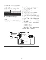
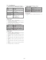
1. T Reel FG Duty Adjustment and CSerr Adjustment
(VC-207 Board)
Adjusting Method:
1)
Set the power switch to VTR (or PLAYER).
2)
Close the cassette compartment without inserting the cassette.
3)
Connect the adjustment remote commander, and set the HOLD
switch to ON (SERVICE position).
4)
Select page: 0, address: 01, and set data: 01.
5)
Select page: C, address: 6A, set data: 10, and press the PAUSE
button of the adjustment remote commander.
6)
Select page: 3, address: 09, set data: 00, and press the PAUSE
button of the adjustment remote commander.
7)
Select page: 3, address: 01, set data: 1A, and press the PAUSE
button of the adjustment remote commander.
8)
Select page: 3, address: 02, and check that the data is changed
from “17” to “00”.
9)
Set the HOLD switch of the adjustment remote commander to
OFF, and wait more than 2 seconds.
10) Set the HOLD switch of the adjustment remote commander to
ON.
11) Check that the data of page: 3, address: 08 and that of page: C,
address: 59 are the same.
12) Select page: 3, address: 03. If the data is “00”, it means that the
CSerr adjustment has ended normally.
13) Check that the data of page: 3, address: 04 and that of page: C,
address: 6F are the same.
14) Select page: C, address: 6F. If the data is “01”, or “02”, “03”, it
means that the T reel FG adjustment has ended normally.
15) Select page: C, address: 6A, set data: 00, and press the PAUSE
button of the adjustment remote commander.
16) Set the data of page: 0, address: 01, and set data: 00.
17) Turn OFF the power supply.
Measurement Point
Measuring Instrument
Adjustment Page
Adjustment Address
Specified Value
Adjustment remote commander
display data
C
59, 6F
T reel FG Duty Adjustment:
The data of page: C, address: 6F is
“01”, or “02” , “03”.
CSerr Adjustment:
The data of page: 3, address: 03 is
“00”.
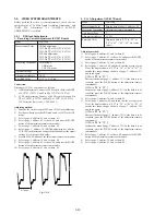
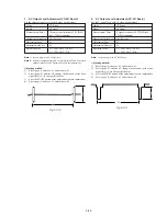
2. Switching Position Adjustment (VC-207 Board)
Mode
Signal
Measurement Point
Measuring Instrument
Adjustment Page
Adjustment Address
Specified Value
Adjusting Method:
1)
Select page: 0, address: 01, and set data: 01.
2)
Select page: 3, address: 01, set data: 0E, and press the PAUSE
button of the adjustment remote commander.
3)
Select page: 3, address: 02, and check that the data is changed
from “0E” to “00”.
4)
Select page: 3, address: 03, and check that the data is “00”.
5)
Set the HOLD switch of the adjustment remote commander to
OFF, and wait more than 2 seconds (so that the adjustment
data is automatically written in page: C, address: 4C to 4F).
6)
Set the HOLD switch of the adjustment remote commander to
ON.
7)
Select page: 0, address: 01, and set data: 00.
8)
Set to the stop mode.
9)
Turn OFF the power supply.
VTR Playback
SW/OL reference tape (XH2-3)
Display data of page: 3, address: 03
Adjustment remote commander
C
4C, 4D, 4E, 4F
The data of page: 3, address: 03 is
“00”.
Содержание Handycam Vision DCR-TRV5
Страница 10: ...1 2 ...
Страница 11: ...1 3 ...
Страница 12: ...1 4 ...
Страница 13: ...1 5 ...
Страница 14: ...1 6 ...
Страница 15: ...1 7 ...
Страница 16: ...1 8 ...
Страница 17: ...1 9 ...
Страница 18: ...1 10 ...
Страница 19: ...1 11 ...
Страница 20: ...1 12 ...
Страница 21: ...1 13 ...
Страница 22: ...1 14 ...
Страница 23: ...1 15 ...
Страница 24: ...1 16 ...
Страница 25: ...1 17 ...
Страница 26: ...1 18 ...
Страница 27: ...1 19 ...
Страница 28: ...1 20 ...
Страница 29: ...1 21 ...
Страница 30: ...1 22 ...
Страница 31: ...1 23 ...
Страница 32: ...1 24 ...
Страница 33: ...1 25 ...
Страница 34: ...1 26 ...
Страница 35: ...1 27 ...
Страница 36: ...1 28 ...
Страница 37: ...1 29E ...
Страница 45: ...DCR TRV5 TRV5E SECTION 3 BLOCK DIAGRAMS 3 1 OVERALL BLOCK DIAGRAM 1 3 1 3 2 3 3 3 4 ...
Страница 46: ...DCR TRV5 TRV5E 3 2 OVERALL BLOCK DIAGRAM 2 3 6 3 7 3 8 DCR TRV5 TRV5E ...
Страница 47: ...DCR TRV5 TRV5E 3 3 POWER BLOCK DIAGRAM 3 9 3 10 3 11 3 12 3 13E ...
Страница 71: ...DCR TRV5 TRV5E 4 75 4 76 4 77 AUDIO PROCESSOR AU 204 ...
Страница 73: ...DCR TRV5 TRV5E 4 81 4 82 AUDIO PROCESS IR TRANSMMITER MA 330 ...
Страница 107: ...ARRANGEMENT DIAGRAM FOR ADJUSTMENT PARTS VC 207 board SIDE A VC 207 board SIDE B 5 26 ...
Страница 131: ...ARRANGEMENT DIAGRAM FOR ADJUSTMENT PARTS VC 207 board SIDE A VC 207 board SIDE B 5 52 ...


