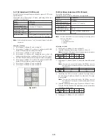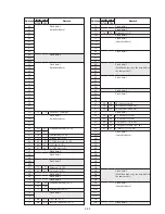
5-20
6. White Balance Adjustment (VF-124 board)
Correct the white balance.
If deviated, the reproduction of the EVF screen may degenerate.
Mode
Camera E-E
Subject
Arbitrary
Measurement Point
Check on EVF screen
Measuring Instrument
Adjustment Page
D
Adjustment Address
71, 72
Specified Value
The EVF screen should not be colored
Adjusting method:
1)
Select page: 0, address: 01, and set data: 01.
2)
Input the following data to page: D, address: 88 to 8D.
Note:
Press the PAUSE button of the adjustment remote commander
each time to set the data.
3)
Select page: D, address: 71 and 72, set the data to the initial
value.
Note:
Press the PAUSE button of the adjustment remote commander
each time to set the data.
4)
Check that the LCD screen is not colored. If colored, change
the data of page: D, address: 71 and 72 so that the EVF screen
is not colored.
Note:
To write in the non-volatile memory (EEPROM), press the
PAUSE button of the adjustment remote commander each time
to set the data.
5)
Input the following data to page: D, address: 88 to 8D.
Note:
Press the PAUSE button of the adjustment remote commander
each time to set the data.
6)
Select page: 0, address: 01, and set data: 00.
Address
Data
88
00
89
27
8A
00
8B
00
8C
00
8D
00
Address
Data
71
80
72
80
Address
Data
88
38
89
00
8A
20
8B
20
8C
02(NTSC)
00(PAL)
8D
00
Содержание Handycam Vision DCR-TRV5
Страница 10: ...1 2 ...
Страница 11: ...1 3 ...
Страница 12: ...1 4 ...
Страница 13: ...1 5 ...
Страница 14: ...1 6 ...
Страница 15: ...1 7 ...
Страница 16: ...1 8 ...
Страница 17: ...1 9 ...
Страница 18: ...1 10 ...
Страница 19: ...1 11 ...
Страница 20: ...1 12 ...
Страница 21: ...1 13 ...
Страница 22: ...1 14 ...
Страница 23: ...1 15 ...
Страница 24: ...1 16 ...
Страница 25: ...1 17 ...
Страница 26: ...1 18 ...
Страница 27: ...1 19 ...
Страница 28: ...1 20 ...
Страница 29: ...1 21 ...
Страница 30: ...1 22 ...
Страница 31: ...1 23 ...
Страница 32: ...1 24 ...
Страница 33: ...1 25 ...
Страница 34: ...1 26 ...
Страница 35: ...1 27 ...
Страница 36: ...1 28 ...
Страница 37: ...1 29E ...
Страница 45: ...DCR TRV5 TRV5E SECTION 3 BLOCK DIAGRAMS 3 1 OVERALL BLOCK DIAGRAM 1 3 1 3 2 3 3 3 4 ...
Страница 46: ...DCR TRV5 TRV5E 3 2 OVERALL BLOCK DIAGRAM 2 3 6 3 7 3 8 DCR TRV5 TRV5E ...
Страница 47: ...DCR TRV5 TRV5E 3 3 POWER BLOCK DIAGRAM 3 9 3 10 3 11 3 12 3 13E ...
Страница 71: ...DCR TRV5 TRV5E 4 75 4 76 4 77 AUDIO PROCESSOR AU 204 ...
Страница 73: ...DCR TRV5 TRV5E 4 81 4 82 AUDIO PROCESS IR TRANSMMITER MA 330 ...
Страница 107: ...ARRANGEMENT DIAGRAM FOR ADJUSTMENT PARTS VC 207 board SIDE A VC 207 board SIDE B 5 26 ...
Страница 131: ...ARRANGEMENT DIAGRAM FOR ADJUSTMENT PARTS VC 207 board SIDE A VC 207 board SIDE B 5 52 ...


