


5-36
Address
B0
B1
B2
B3
B4
B5
B6
B7
B8
B9
BA
BB
BC
BD
BE
BF
C0
C1
C2
C3
C4
C5
C6
C7
C8
C9
CA
CB
CC
CD
CE
CF
D0
D1
D2
D3
D4
D5
D6
D7
D8
D9
DA
DB
DC
DD
DE
DF
E0
E1
E2
E3
E4 to FF
Initial value
NTSC
PAL
Remark
Fixed data-1
(Initialized data)
Fixed data-2
(Modified data, copy the data built in
the same model.)
Fixed data-1
(Initialized data)
Fixed data-2
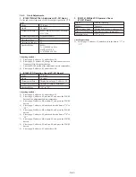
4. Initializing the C Page Data
Note:
If the page C data is initialized, the following adjustments must be
performed again.
1) Modification of C page data
2) Servo system adjustments
3) All RF block adjustments of the video system adjustments
Adjusting page
C
Adjusting Address
00 to 6F
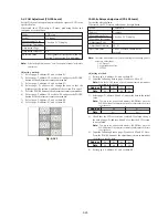
Initializing Method:
1)
Select page: 0, address: 01, and set data: 01.
2)
Select page: 4, address: 02, set data: 01, and press the PAUSE
button of the adjustment remote commander.
3)
Check that the data of page: 4, address: 02 changes in order of
“01”, “03”, “05”, “00”.
4)
Perform “Modification of C Page Data”.
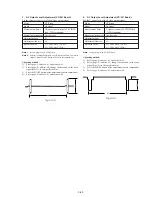
5. Modification of C Page Data
If the C Page data has been initialized, change the data of the “Fixed
data-2” address shown in the following table by manual input.
Modifying Method:
1)
Before changing the data, select page: 0, address: 01, and set
data: 01.
2)
New data for changing are not shown in the tables because
they are different in destination. When changing the data, copy
the data built in the same model.
Note:
If copy the data built in the different model, the camcorder
may not operate.
3)
When changing the data, press the PAUSE button of the
adjustment remote commander each time when setting new
data to write the data in the non-volatile memory.
4)
Check that the data of adjustment addresses is the initial value.
If not, change the data to the initial value.
5)
After changing the data, select page: 0, address: 01, and set
data: 00.
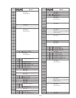
6. C Page Table
Note:
Fixed data-1 : Initialized data. ( Refer to “4. Initializing the C Page
Data”.)
Fixed data-2 : Modified data. (Refer to “5. Modification of C PAGE
Data”).
Address
00
01
02
03
04
05
06
07
08
09
0A
0B
0C
0D
0E
0F
10
11
Initial value
NTSC
PAL
Remark
Fixed data-1
Fixed data-2
Fixed data-1
Fixed data-2
Fixed data-1
Table 5-3-2.
Содержание Handycam Vision DCR-TRV5
Страница 10: ...1 2 ...
Страница 11: ...1 3 ...
Страница 12: ...1 4 ...
Страница 13: ...1 5 ...
Страница 14: ...1 6 ...
Страница 15: ...1 7 ...
Страница 16: ...1 8 ...
Страница 17: ...1 9 ...
Страница 18: ...1 10 ...
Страница 19: ...1 11 ...
Страница 20: ...1 12 ...
Страница 21: ...1 13 ...
Страница 22: ...1 14 ...
Страница 23: ...1 15 ...
Страница 24: ...1 16 ...
Страница 25: ...1 17 ...
Страница 26: ...1 18 ...
Страница 27: ...1 19 ...
Страница 28: ...1 20 ...
Страница 29: ...1 21 ...
Страница 30: ...1 22 ...
Страница 31: ...1 23 ...
Страница 32: ...1 24 ...
Страница 33: ...1 25 ...
Страница 34: ...1 26 ...
Страница 35: ...1 27 ...
Страница 36: ...1 28 ...
Страница 37: ...1 29E ...
Страница 45: ...DCR TRV5 TRV5E SECTION 3 BLOCK DIAGRAMS 3 1 OVERALL BLOCK DIAGRAM 1 3 1 3 2 3 3 3 4 ...
Страница 46: ...DCR TRV5 TRV5E 3 2 OVERALL BLOCK DIAGRAM 2 3 6 3 7 3 8 DCR TRV5 TRV5E ...
Страница 47: ...DCR TRV5 TRV5E 3 3 POWER BLOCK DIAGRAM 3 9 3 10 3 11 3 12 3 13E ...
Страница 71: ...DCR TRV5 TRV5E 4 75 4 76 4 77 AUDIO PROCESSOR AU 204 ...
Страница 73: ...DCR TRV5 TRV5E 4 81 4 82 AUDIO PROCESS IR TRANSMMITER MA 330 ...
Страница 107: ...ARRANGEMENT DIAGRAM FOR ADJUSTMENT PARTS VC 207 board SIDE A VC 207 board SIDE B 5 26 ...
Страница 131: ...ARRANGEMENT DIAGRAM FOR ADJUSTMENT PARTS VC 207 board SIDE A VC 207 board SIDE B 5 52 ...