background image

4-58

CCD-TRV107E/TRV108E/TRV208E/TRV408E

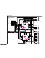
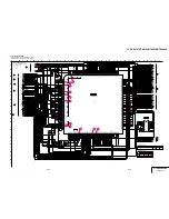
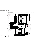
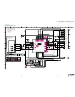
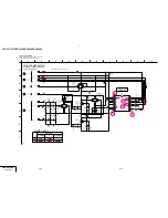
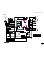
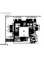
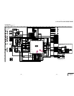
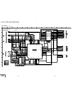
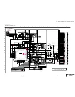
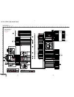
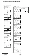
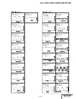
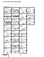
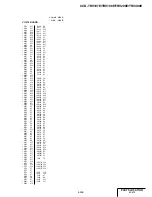
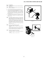
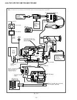
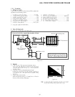
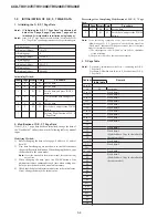
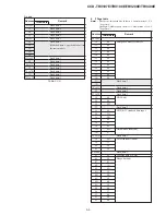
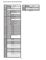
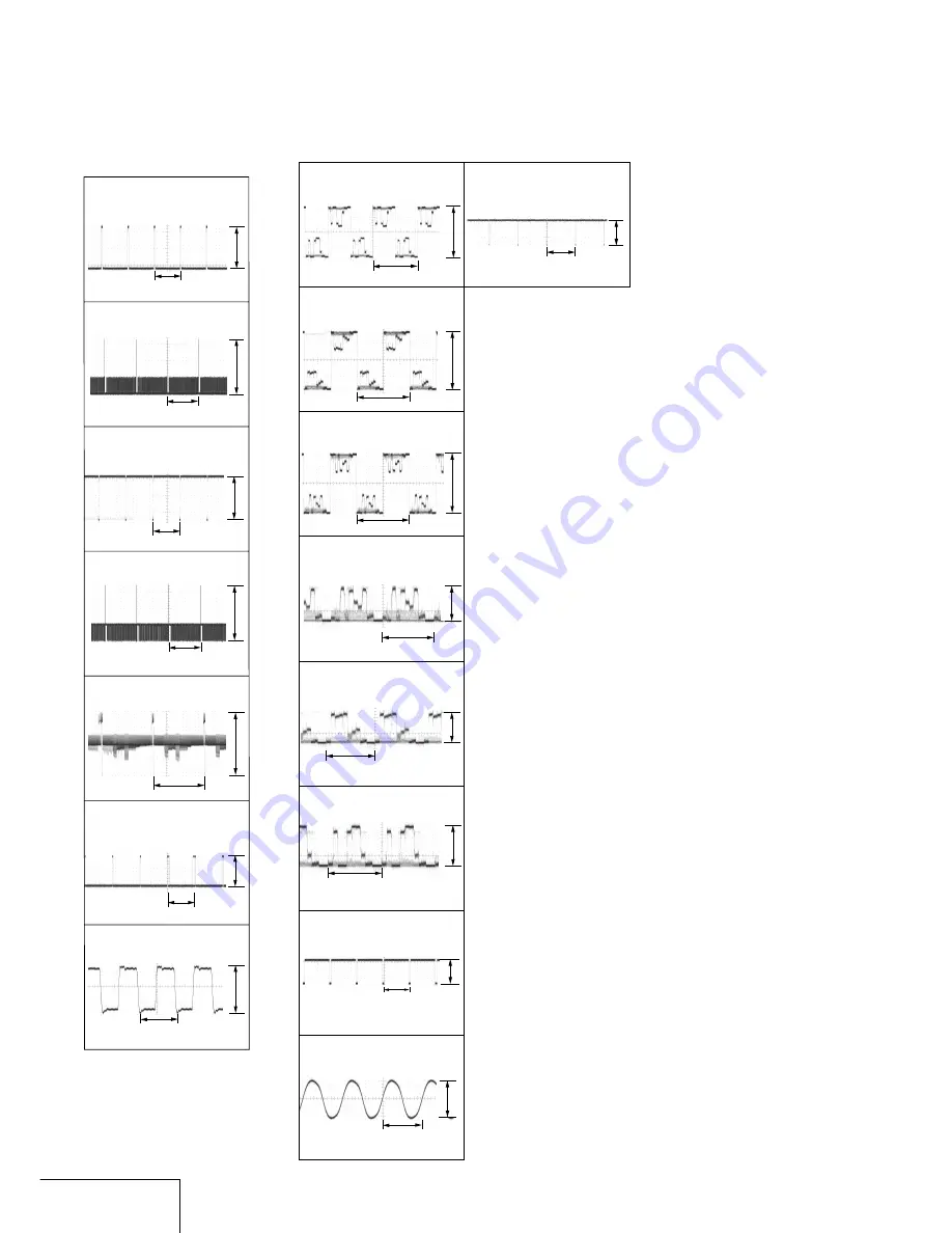
4-3. WAVEFORMS

CD-354 

BOARD

CAMERA REC

2

 IC2191 

2

3

 IC2191 

3

4

 IC2191 

4

5.4Vp-p

H

H

17.5Vp-p

5

 IC2191 

7


2.0Vp-p

19.0Vp-p

H

3.4Vp-p

6

 IC2191 

q;

7

 IC2191 

qdqf

1

 IC2191 

1

5.3Vp-p

H

17.5Vp-p

20 msec

20 msec

105 nsec

V

9

 IC2002 

rk

2H

2H

2H

91nsec

VF-150 

BOARD

2

 IC2001 

ws

1

 IC2001 

w;

7.4Vp-p

7.5Vp-p

3.1Vp-p

3.1Vp-p

3

 IC2001 

wf

7.4Vp-p

4

 IC2001 

rh

H

H

H

0.4Vp-p

5

 IC2001 

rj

0.4Vp-p

7

 IC2002 

1

6

 IC2001 

rk

H

2.2Vp-p

8

 IC2002 

wh

0.4Vp-p

WAVEFORMS

CD-354, VF-150

Содержание Handycam Vision CCD-TRV107E

Страница 1: ...tical 460 Digital CCD TRV208E TRV408E 20 Optical 560 Digital Focal length 3 6 72 mm 5 32 2 7 8 in When converted to a 35 mm still camera 41 820 mm 1 5 8 32 3 8 in Colour temperature Auto Minimum illumination 0 3 lx lux F 1 4 0 lx lux in the NightShot mode Objects unable to be seen due to the dark can be shot with infrared lighting CCD TRV107E TRV108E TRV208E 1 lx lux F 1 4 CCD TRV408E Input output...

Страница 2: ...ular size LEAD FREE MARK Unleaded solder has the following characteristics Unleaded solder melts at a temperature about 40 C higher than ordinary solder Ordinary soldering irons can be used but the iron tip has to be applied to the solder joint for a slightly longer time Soldering irons using a temperature regulator should be set to about 350 C Caution The printed pattern copper foil may peel away...

Страница 3: ...CCD TRV107E JE TRV408E JE only 0 2 pin conversion adaptor 1 CCD TRV107E E HK TRV408E E HK only 0 9 SUPPLIED ACCESSORIES Make sure that the following accessories are supplied with your camcorder Abbreviation AUS Australian model HK Hong Kong model CH Chinese model JE Tourist model EE East European model NE North European model RU Russian model Table for difference of function Model Destination Remo...

Страница 4: ...DISASSEMBLY 2 1 VIDEO LIGHT 2 2 2 2 LCD SECTION PD 156 BOARD 2 3 2 3 VF 150 LB 073 BOARDS 2 4 2 4 FRONT PANEL SECTION SI 033 BOARD 2 5 2 5 CABINET L SECTION 2 6 2 6 CABINET R SECTION 2 7 2 7 EVF SECTION 2 7 2 8 BATTERY PANEL SECTION 2 8 2 9 LENS SECTION 2 8 2 10 VC 272 BOARD 2 9 2 11 CONTROL SWITCH BLOCK CF 2000 2 9 2 12 MECHANISM DECK 2 12 2 13 HINGE ASSEMBLY 2 12 2 14 CIRCUIT BOARDS LOCATION 2 1...

Страница 5: ... RGB AMP Adjustment PD 156 board 5 25 3 Contrast Adjustment PD 156 board 5 26 4 COM AMP Adjustment PD 156 board 5 26 5 V COM Adjustment PD 156 board 5 27 6 White Balance Adjustment PD 156 board 5 27 5 2 MECHANISM SECTION ADJUSTMENT 5 28 2 1 ADJUSTMENT REMOTE COMMANDER 5 28 2 2 OPERATING WITHOUT CASSETTE 5 28 2 3 TAPE PATH ADJUSTMENT 5 28 1 Preparations for Adjustment 5 28 5 3 VIDEO SECTION ADJUSTM...

Страница 6: ...ASSETTE COMPARTMENT ASSY DRUM ASSY 6 8 6 1 9 LS CHASSIS BLOCK ASSEMBLY 6 9 6 1 10 MECHANICAL CHASSIS BLOCK ASSEMBLY 1 6 10 6 1 11 MECHANICAL CHASSIS BLOCK ASSEMBLY 2 6 11 6 2 ELECTRICAL PARTS LIST 6 12 Color reproduction frame is shown on page 215 ...

Страница 7: ...0 4 Refer to 2 6 to remove the cassette lid assembly 5 Refer to 2 6 to remove the cabinet L assembly 6 Disconnect CN704 2P of VC 272 board 7 Add 5V from the DC POWER SUPPLY and unload with a pressing the cassette compartment SERVICE NOTE 8 Pull the timing belt in the direction of arrow A with a pincette while pressing the cassette compartment take care not to damage to adjust the bending of a tape...

Страница 8: ...n the past 3 1 Display Method While pressing the STOP key set the switch from OFF to PLAYER and continue pressing the STOP key for 5 seconds continuously The service mode will be displayed and the counter will show the backup No and the 5 character self diagnosis codes 3 2 Switching of Backup No By rotating the control dial past self diagnosis codes will be shown in order The backup No in the indi...

Страница 9: ...pe again and perform operations from the beginning Load the tape again and perform operations from the beginning Load the tape again and perform operations from the beginning Load the tape again and perform operations from the beginning Load the tape again and perform operations from the beginning Load the tape again and perform operations from the beginning Load the tape again and perform operati...

Страница 10: ...n Inspect the lens block focus reset sensor Pin qs of CN301 of VC 272 board when focusing is performed when the control dial is rotated in the focus manual mode and the focus motor drive circuit IC301 of VC 272 board when the focusing is not performed Inspect the lens block zoom reset sensor Pin qf of CN301 of VC 272 board when zooming is performed when the zoom switch is operated and the zoom mot...

Страница 11: ...assette compartment by pressing the mark on the cassette compartment The cassette compartment automatically goes down Close the lid of the cassette compartment 1Open the lid of the cassette compartment and press Z EJECT The cassette compartment opens automatically 2Insert a cassette into the cassette compartment with its window facing out and the write protect tab on the cassette up EJECT 9 Record...

Страница 12: ...го света на экран ЖКД видоискатель или объектив в течение длительного периода времени может привести к неисправностям c Не направляйте камеру прямо на солнце Это может привести к неисправности Вашей видеокамеры Проводите съемки солнца в условиях низкой освещенности таких как сумерки d Using this manual Precautions on camcorder care Lens and LCD screen finder on mounted models only The LCD screen a...

Страница 13: ...ates the recording time with the viewfinder Until your camcorder calculates the actual remaining battery time min appears in the display window While charging the battery pack no indicator appears or the indicator flashes in the display window in the following cases The AC power adaptor is disconnected The battery pack is not installed properly Something is wrong with the battery pack We recommend...

Страница 14: ...чтобы мeню иcчeзло Появитcя индикaтоp вpeмeни Step 2 Setting the date and time Set the date and time settings when you use your camcorder for the first time CLOCK SET will be displayed each time when you set the power switch to CAMERA unless you set the date and time settings If you do not use your camcorder for about 6 months the date and time settings may be released bars may appear because the ...

Страница 15: ... while pressing the small green button Your camcorder is set to the standby mode 4 Open the LCD panel while pressing OPEN The viewfinder automatically turns off 5 Press START STOP Your camcorder starts recording The REC indicator appears The recording lamp located on the front of your camcorder lights up To stop recording press START STOP again The recording lamp lights up in the viewfinder when y...

Страница 16: ...бaтapeйный блок от видeокaмepы во избeжaниe cлyчaйного включeния вcтpоeнной подcвeтки Использование функции тpaнcфокaции Heмного пepeдвиньтe pычaг пpиводa тpaнcфокaтоpa для мeдлeнной тpaнcфокaции Пepeдвиньтe eго дaльшe для ycкоpeнной тpaнcфокaции Иcпользовaниe yмepeнного yвeличeния обecпeчивaeт наилучшие результаты Сторона Т для телефото объект приближается Сторона W для широкоугольного вида объек...

Страница 17: ...e cancelled BACK LIGHT 34 NIGHTSHOT OFF ON Запись изображения Recording a picture Infrared rays emitter Излyчaтeль инфpaкpacныx лyчeй Съемка в темноте NightShot Фyнкция NightShot позволяeт Baм выполнять cъeмкy объeктов в тeмныx мecтax Haпpимep пpи иcпользовaнии дaнной фyнкции Bы можeтe c ycпexом выполнять cъeмкy ночныx животныx для нaблюдeния В то время когда ваша видеокамера находится в режиме CA...

Страница 18: ...itor the sound from the speaker Notes If you start recording after using the end search function occasionally the transition between the last scene you recorded and the next scene may not be smooth Once you eject the cassette after you have recorded on the tape the end search function does not work 38 3 6 2 5 4 VOLUME 1 C A M E R A PL A Y E R O F F C H G POWER REW PLAY Воспроизведение Основные пол...

Страница 19: ...UT A V OUT S VIDEO VIDEO AUDIO IN Просмотр записи на экране телевизора Для пpоcмотpa воcпpоизводимого изобpaжeния нa экpaнe тeлeвизоpa подcоeдинитe видeокaмepy к тeлeвизоpy c помощью cоeдинитeльного кaбeля ayдио видeо котоpый вxодит в комплeкт поcтaвки видeокaмepы Bы можeтe иcпользовaть кнопки yпpaвлeния воcпpоизвeдeниeм тaким жe cпоcобом кaк пpи yпpaвлeнии воcпpоизводимым изобpaжeниeм нa экpaнe Ж...

Страница 20: ...о режима In CAMERA mode set 16 9WIDE to CINEMA or 16 9FULL in in the menu settings p 79 To cancel the wide mode Set 16 9WIDE to OFF in the menu settings If the wide mode is set to 16 9FULL CCD TRV408E only The SteadyShot function does not work If you select 16 9FULL in the menu settings when the SteadyShot function is working flashes and the SteadyShot function does not function In the wide mode Y...

Страница 21: ...функции эффекта изображения Установите команду P EFFECT в положение OFF в меню установок Пpи ycтaновкe пepeключaтeля POWER в положeниe OFF CHG Ваша видеокамера автоматически вернется в обычный режим Using special effects Picture effect 1 In CAMERA mode select P EFFECT in in the menu settings p 79 2 Select the desired picture effect mode in the menu settings then press the SEL PUSH EXEC dial To can...

Страница 22: ...Регулировка экспозиции вручную Вы можете отрегулировать и установить экспозицию вручную Отрегулируйте экспозицию вручную в следующих случаях Объект на фоне задней подсветки Яркий объект на темном фоне Для записи темных изображений например ночных сцен с большой достоверностью 1 В режиме CAMERA нажмите кнопку EXPOSURE На экране появится индикатор экспозиции 2 Поверните диск SEL PUSH EXEC для регули...

Страница 23: ...ed language and return to step 2 1 2 3 4 TITLE S I Z E SMA L L VACATION S I Z E L ARGE PRESE T T I T L E HE L LO HAPPY B I RTHDAY HAPPY HOL I DAYS CONGRA TU L A T I ONS OUR SWEE T BABY WEDD I NG VACA T I ON THE END T I T L E END PRESE T T I T L E HE L LO HAPPY B I RTHDAY HAPPY HOL I DAYS CONGRA TU L A T I ONS OUR SWEE T BABY WEDD I NG VACA T I ON THE END T I T L E END PRESE T T I T L E HE L LO HAP...

Страница 24: ...proceed from step 1 We recommend setting the POWER switch to PLAYER or removing the cassette so that your camcorder does not automatically turn off while you are entering title characters If you select The menu for selecting alphabet and Russian characters appears Select to return to the previous screen To erase a character Select C The last character is erased To enter a space Select Z then selec...

Страница 25: ...eомaгнитофонa используя видеокамеру в качестве проигрывателя Установите опцию DISPLAY в положение LCD в в установках меню Установка по умолчанию соответствует LCD Heобxодимо чтобы индикaтоpы иcчeзли инaчe они бyдyт зaпиcaны нa лeнтy Добeйтecь того чтобы индикaтоpы иcчeзли нaжимaя кнопки DISPLAY нa видeокaмepe DISPLAY нa пyльтe диcтaнционного yпpaвлeния только модeли CCD TRV107E TRV208E TRV408E 1 В...

Страница 26: ...pa SETUP a зaтeм нaжмитe нa диcк 5 Повepнитe диcк SEL PUSH EXEC для выбоpa PAUSE MODE a зaтeм нaжмитe нa диcк 6 Повepнитe диcк SEL PUSH EXEC чтобы выбpaть peжим для отмeны пayзы пpи зaпиcи нa видeомaгнитофонe a зaтeм нaжмитe нa диcк Пpоcтaя пepeзaпиcь лeнты Пpоcтaя пepeзaпиcь Dubbing a tape easily Easy Dubbing Step 2 Setting the VCR to operate with your camcorder You can control the VCR by wireles...

Страница 27: ...HELLO T I T L E HELLO T I T L E BB I NG U D Y S A E BB I NG U D Y S A E BB I NG U D Y S A E BB I NG U D Y S A E EASY DUBBING START T I T LE SEL MODE SEL SETUP OFF NORMAL 0 0 0 0 0 EASY DUBBING T I T LE SEL OFF 0 0 0 0 0 0 0 0 0 0 0 0 0 0 0 0 0 0 0 0 0 0 0 0 0 O L L E H Y A D H T R I B Y P P A H S Y A D I L O H Y P P A H S N O I T A L U T A R G N O C OUR SWEE T BABY EASY DUBBING T I T LE SEL OFF 0 ...

Страница 28: ... display disappear Press MENU 1 CAMERA 2 3 4 PLAYER MENU MANUA L SE T PROGRAM AE P E F F ECT MENU END MANUA L SE T MENU END MANUA L SE T PROGRAM AE P E F F ECT OTHERS WOR L D T I ME BEEP 0 HR OTHERS WOR L D T I ME BEEP REC L AMP RE TURN ON OF F D I SP L AY COMMANDER ED I T TBC DNR NTSC PB OTHERS WOR L D T I ME BEEP D I SP L AY REC L AMP COMMANDER OTHERS ON WOR L D T I ME BEEP REC L AMP RE TURN D I...

Страница 29: ...n the LCD screen turn the SEL PUSH EXEC dial to adjust the following bar To set the brightness in the viewfinder normal To brighten the viewfinder POWER switch PLAYER CAMERA PLAYER CAMERA To reduce intensity To increase intensity Mode z BRT NORMAL BRIGHT 82 Notes on DEMO MODE You cannot select DEMO MODE when a cassette is inserted in your camcorder DEMO MODE is set to STBY Standby at the factory a...

Страница 30: ...ностей In the recording and playback modes Symptom Cause and or Corrective Actions The battery pack is not installed or is dead or nearly dead c Install a charged battery pack p 15 16 The AC power adaptor is not connected to a wall socket c Connect the AC power adaptor to a wall socket p 20 The tape was ejected after recording You have not recorded on the cassette yet The operating temperature is ...

Страница 31: ...1 95 Troubleshooting Поиск и устранение неисправностей Warning indicators and messages Warning messages CLOCK SET Set the date and time p 22 FOR InfoLITHIUM Use an InfoLITHIUM battery pack p 105 BATTERY ONLY Q NO TAPE 1 Insert a cassette tape Q TAPE END 1 The tape has reached the end CLEANING CASSETTE 2 The video heads are dirty p 109 START STOP KEY Press START STOP to activate the ORC setting Thi...

Страница 32: ...яется водостойким Индикатор времени оставшегося заряда батарейного блока Ecли питaниe отключaeтcя xотя индикатор времени оставшегося заряда батарейного блока указывает на то что батарейный блок достаточно заряжен для функционирования видеокамеры снова зарядите батарейный блок полностью так чтобы индикация времени оставшегося заряда батарейного блока была правильной Заметьте тем не менее что точная...

Страница 33: ...peдно появляютcя индикaтоp x и cообщeниe CLEANING CASSETTE или мигaeт индикaтоp x Воспроизводимое изображение содержит помехи Воспроизводимое изображение с трудом различимо Воспроизводимое изображение не появляется на экране a Heмного зaгpязнeны b Cильно зaгpязнeны В случае возникновения указанных выше проблем почистите видеоголовки с помощью чиcтящeй кacceты Sony V8 25CLD пpиобpeтaeтcя дополнитeл...

Страница 34: ...t Sand or dust may cause your camcorder to malfunction and sometimes this malfunction cannot be repaired Maintenance information and precautions 114 Сетевой адаптер переменного тока Отсоедините аппарат от электрической сети если он не используется длительное время Для отсоединения сетевого шнура потяните его за разъем Никогда не тяните за сам шнур Не эксплуатируйте аппарат с поврежденным шнуром ил...

Страница 35: ...eздо DC IN cтp 16 20 0 Кpючки для плeчeвого peмня cтp 119 Camcorder Quick Reference Identifying the parts and controls 1 Eyecup 2 Viewfinder lens adjustment lever p 31 3 V BATT release lever p 15 4 OPEN button p 26 5 SEL PUSH EXEC dial p 22 77 6 Power zoom lever p 30 7 POWER switch p 26 8 START STOP button p 26 9 DC IN jack p 16 20 q Hooks for shoulder strap p 119 Attaching the shoulder strap Atta...

Страница 36: ...e Commander and your camcorder function identically to the buttons on your camcorder Identifying the parts and controls 1 Transmitter Point toward the remote sensor to control the camcorder after turning on the camcorder 2 Tape transport buttons p 40 3 DISPLAY button p 39 4 START STOP button p 26 5 Power zoom button p 30 1 2 3 5 4 125 Quick Reference Оперативный справочник Для подготовки пульта ди...

Страница 37: ...ов qa Индикaтоp выключeнной ycтойчивой cъeмки Tолько модeль CCD TRV408E cтp 85 qs Индикaтоp pyчной фокycиpовки cтp 55 qd Индикaтоp вcтpоeнной подcвeтки cтp 62 qf Индикaтоp STBY REC cтp 26 Индикaтоp peжимa yпpaвлeния видeоизобpaжeниeм cтp 40 qg Индикaтоp cчeтчикa лeнты cтp 32 индикaтоp фyнкции caмодиaгноcтики cтp 100 qh Индикaтоp оcтaвшeйcя лeнты cтp 32 qj Индикaтоp END SEARCH cтp 37 qk Индикaтоp N...

Страница 38: ...4 Front panel section SI 033 board 2 7 EVF section 2 8 Battery panel section 2 9 Lens section 2 10 VC 272 board 2 11 Control switch block CF 2000 2 12 Mechanism deck 2 13 Hinge assembly 2 5 Cabinet L section 2 6 Cabinet R section SI 033 board service position Mechanism deck service position Note Use the parts only which can be removed easily from outside of the mechanism deck Service position to c...

Страница 39: ...CPC connector CONNECTION OF EQUIPMENT Adjustment remote commander RM 95 Info lithium battery L series AC IN CPC jig for SB J 6082 539 A AC power adaptor MI screw M2 4 H CPC lid CN713 Conductor side 16 1 Claw 1 Push in the dent inside hole with wire tip A 3 Remove in the direction of the arrow A 4 Halogen lamp 2 Video light ...

Страница 40: ...board 7 Liquid crystal indicator module 8 Back light Cold cathode fluorescent tube Liquid crystal indicator module Back light Cold cathode fluorescent tube PD 156 BOARD SERVICE POSITION AC IN AC power adaptor Multi CPC jig J 6082 311 A 2 Two MI screws M2 4 H q Indication LCD block assembly 20P LCD holder 3 Two claws 9 Two claws Adjustment remote commander RM 95 Info lithium battery L series CPC ji...

Страница 41: ...board VF lens B assembly 7 VF lens B assembly 4 Claw 8 Caution Before disengaging the 2 claws in step 7 hold the EVF lens facing downward and then disengage the 2 claws very slowly and carefully so that the internal 2 plastic sheets must not drop Keep them in place with an appropriate piece of sheet so that hey do not drop out of their positions VF 150 LB 073 BOARDS SERVICE POSITION Adjustment rem...

Страница 42: ...o MI screws M2 4 H 4 Two MI screws M2 4 H 5 Two claws 6 Front panel section Front panel section SI 033 board Adjustment remote commander RM 95 Info lithium battery L series CPC jig for SB J 6082 539 A AC IN AC power adaptor SI 033 BOARD SERVICE POSITION Remove it while taking care as the FP 418 flexible cable is connected ...

Страница 43: ...ette lid assembly MECHANISM DECK SERVICE POSITION Note Use the parts only which can be removed easily from outside of the mechanism deck AC power adaptor AC IN Press the cassette compartment in the direction of the arrow A to move it up in the direction of the arrow B How to move up the cassette compartment manually Adjustment remote commander RM 95 Info lithium battery L series CPC jig for SB J 6...

Страница 44: ...T R SECTION 1 MI screw M2 4 H 2 MI screw M2 4 H 3 Three MI screws M2 4 H 4 Control switch block CF 2000 22P 5 Harness PD 115 20P 6 Cabinet R section 2 7 EVF SECTION 3 MI screw M2 4 H 4 EVF section 1 FP 401 flexible board 20P 2 Three tapping screws B2 5 ...

Страница 45: ...S 2000 5P 3 Claw 6 Screw 5 Control switch block SS 2000 2 Strap sheet metal lower 1 Battery terminal board 6P 3 Battery terminal board REMOVING THE BATTERY TERMINAL BOARD AND CONTROL SWITCH BLOCK SS 2000 4 Two screws M2 3 lock ace p2 3 Screw M2 3 lock ace p2 5 Claw 6 1 FP 400 flexible board 14P 2 Flexible board from lens block 24P 1 Two tapping screws B2 5 2 Lens frame 3 Lens section ...

Страница 46: ...H BLOCK CF 2000 VC 272 1 Two screws M2 3 lock ace p2 5 Screw M2 3 lock ace p2 8 VC 272 board 3 Two screws M2 3 lock ace p2 2 MD frame B 4 FP 397 flexible board 7 Control switch block FK 2000 12P 6 Claw 2 Six tapping screws B2 5 1 Harness PD 115 6P 3 Control switch block CF 2000 ...

Страница 47: ...the VTR Section To check the VTR section set the VTR to the Forced VTR power ON mode Operate the VTR functions using the adjustment remote commander with the HOLD switch set in the OFF position Note If the machine malfunctions the operating mode changes by itself connect the FK 2000 block CF 2000 block Setting the Forced VTR Power ON mode 1 Select page 0 address 01 and set data 01 2 Select page D ...

Страница 48: ...Section To check the camera section set the camera to the Forced camera power ON mode Note If the machine malfunctions the operating mode changes by itself connect the FK 2000 block CF 2000 block Setting the Forced Camera Power ON mode 1 Select page 0 address 01 and set data 01 2 Select page D address 10 set data 01 and press the PAUSE button of the adjustment remote commander Exiting the Forced C...

Страница 49: ...trol switch block FK 2000 2 Claw A A 1 Tapping screw B2 5 3 Four tapping screws B2 5 A A B Be sure that each harness does not go across the ribs of the guide Attach the harness clamp so that the black harness 6P comes to the forefront B 4 2 Hinge blind 5 Four claws 8 Harness clamp 9 Harness PD 115 q Screw M1 7 2 5 qa Control switch block PR 10000 6 Hinge cover C 7 Hinge cover M qs Hinge assembly H...

Страница 50: ...V408E SI 033 STEADY SHOT MIC CD 354 CCD IMAGER PD 156 RGB DRIVE TIMING GENERATOR LCD DRIVE BACK LIGHT DRIVE VC 272 CAMERA VIDEO AUDIO SERVO HI MODE CONTROL D D CONVERTER LB 073 BACK LIGHT VF 150 RGB DRIVE TG 2 14 CIRCUIT BOARDS LOCATION ...

Страница 51: ... 401 CONTROL SWITCH BLOCK FK 2000 CONTROL SWITCH BLOCK CF 2000 CONTROL SWITCH BLOCK SS 2000 CONTROL SWITCH BLOCK PR 10000 FP 397 FP 400 FP 394 FP 418 2 15 FLEXIBLE BOARDS LOCATION The flexible boards contained in the mechanism deck are not shown ...

Страница 52: ...SECTION 3 BLOCK DIAGRAMS 3 1 CCD TRV107E TRV108E TRV208E TRV408E ...

Страница 53: ...RATOR 4 42 IC101 REC PB AMP 4 35 IC272 4 38 IC151 S H GCA A D CONV CAMERA Y C PROCESS VTR Y C PROCESS ATF FOCUS ZOOM MOTOR CONTROL 4 44 IC2301 VIDEO OUTPUT Y CCD OUT IC251 4 17 IC750 REMOTE COMMANDER RECEIVER LED DRIVE 4 38 IC153 CHARACTER GENERATOR 4 52 IC601 D A CONVERTER EVR 4 51 IC351 AFM AUDIO PROCESS SPEAKER AMP AMP DRIVE HALL AMP FOCUS MOTOR DRIVE ZOOM MOTOR DRIVE M905 FOCUS MOTOR M906 ZOOM...

Страница 54: ...ODE CONTROL XEJECT SW KEY AD0 1 ZOOM AD BACKUP VCC CAMERA VIDEO AUDIO SERVO CONTROL SIG MECHA CAMERA CONTROL CAP PWM MT 4 75V OSD SO OSD SCK CH SO XCH SCK IRIS PWM HALL AD ZOOM RST SENS FC RST SENS YAW AD PITCH AD PLA GLASS BATT UNREG VTR UNREG VL UNREG D 2 8V A 2 8V AU 2 8V CAM DD ON VTR DD ON CAM DD ON FAST CHARGE BEEP KEY AD5 BATT SIG BATT EXT ZOOM AD D 1 5V F004 F002 DC DC CONVERTER DRUM CAPST...

Страница 55: ...TIMING ADCLK ADCK AVDD DVDD DRVDD HDRST SYS V A 2 8V A 2 8V A 2 8V D AGC D9 ı D0 CLPOB AD1 AD10 XCH SCK CH SO XCS CH XRST IC151 SYS V PB C RF CLP1 MCK CL ADCK XSG1 XV1 ID PBLK V STOP AHD AVD IC151 C OUT IC151 Y OUT XCH SCK IC402 IC402 IC402 IC402 IC402 IC402 IC402 IC402 IC402 IC402 IC402 IC503 IC503 IC503 CH SO XCS CH SYS V XRST IC151 XCS IC151 CK CONT1 CK CONT2 XVC SCK VC SO VC SI V JACK IN XS JA...

Страница 56: ...VC3 BLKA VC2 VC1 VC0 CLK XCS DATA XPCL VI VDO TBC VD XOSD SCK XOSD SCK XCS OSD XCS OSD OSD SO OSD SO XSYS RST XSYS RST MODE CONTROL IC503 IC503 IC503 IC503 REC RF Y C AFT RF AGC OUT Q105 107 SW AGC SLOW PB C RF IC402 IC601 RF AGC CONT XRF AGC OFF 4 42 REC PB AMP Y C ATF IN PB Y AGC TC RF AGC IN AGC LPF GCA MIX AMP SW SW REC AMP PB AMP PB RF REC AFM IC402 RP PB MODE IC402 BOTH REC DOP REC L CONT RP...

Страница 57: ...10 CAMERA VIDEO 2 2 PAGE 3 10 AUDIO PAGE 3 18 XRST IC151 XCS IC151 CK CONT1 CK CONT2 VC SI VC SO VC SCK XCC DOWN DEW AD XSYS RST XCS VC HI SO ZOOM VR AD HI SI XHI SCK SYS V VC RF SWP XCS AU VC SI VC SO VC SCK VC SI VC SO XVC SCK XCS IC151 SYS V VC RF SWP JOG VD SWP DIR CK CONT1 BOTH REC RP PB MODE XFE ON X1 2 SWP XTBC V RESET XRST IC151 MECHA VD TBC VD MECHA HD MECHA FLD CK CONT2 XSG V RST DA STB ...

Страница 58: ...7 8 9 10 9 10 DRUM VS DRUM ON DRUM START VTR UNREG D 2 8V VCC1 VCC2 COM STBY CONTROL LOGIC DRUM MOTOR DRIVE 4 46 5 6 VS OUTPUT DRIVE BUFFER OUTPUT DRIVE SELSLP2 RF R458 460 DRUM DRIVE CURRENT SENS U V W DRUM FG PG WAVE SHAPER 4 46 4 45 4 45 6 6 DRUM FG DRUM PG WAVE SHAPER LPF V REF WAVE SHAPER 1 2 3 1 2 3 4 4 CN706 COM U V W FG FG PG COM PG FG PG M901 DRUM MOTOR 1 2 M902 CAPSTAN MOTOR CAP U CAP V ...

Страница 59: ... SCK ZOOM VR AD VTR CAMERA CONTROL BEEP AUDIO XSYS RST XCS OSD OSD SO XOSD SCK V JACK IN XS JACK IN CAM DD ON CAMERA VIDEO 2 CAMERA VIDEO 1 BATT SIG CAM DD ON INIT CHARGE ON FAST CHARGE BATT XEXT SW VTR DD ON POWER REFER TO POWER 1 2 XTALLY LED EVF FP 401 3 8 BATT UNREG F001 VTR UNREG F002 PAGE 3 21 PAGE 3 19 PAGE 3 24 IC503 IC502 PAGE 3 11 PAGE 3 18 PAGE 3 9 PAGE 3 8 CN705 XSYS RST KEY AD5 LCD PD...

Страница 60: ...MOD NR MX MTX NR SP VCC Q354 1 2 SPEAKER AMP BUS DECODER AGC MIC L IR L LINE R HP R POWER MUTE SP SP AU 4 75V AU 2 8V MT 4 75V ON OFF MUTE SWITCH Q355 1 2 XCS AU XVC SCK VC SO Q355 2 2 VC 272 BOARD IC351 IC251 PAGE 3 10 16 VC SI VC RF SWP 3 9 47 IC402 104 IC402 80 IC402 79 IC402 78 IC402 VC RF SWP XCS AU VC SI VC SO VC SCK VTR CAMERA CONTROL PAGE 3 11 36 56 IC503 BEEP MODE CONTROL PAGE 3 16 A V OU...

Страница 61: ... 8 9 10 11 VCO VCO XP SAVE 45 XC SAVE 38 LCD DRIVER 4 23 IC5501 TIMING GENERATOR 4 23 IC5502 1 5 2 3 10 C5606 S001 T5601 INVERTER TRANSFORMER BL DET 6 3 5 4 6 7 1 2 INH Q5601 5 4 4 25 IC5602 4 25 IC5601 RECT D5601 INVERTER DRIVE Q5602 L5601 RES 19 SPD 24 CLD 23 CTR 22 PSS2 21 PSS1 20 EX2 18 PSG 17 MODE2 16 MODE1 15 EX1 14 SPS 13 CLS RES SPD CLD CTR PSS2 PSS1 EX2 PSG MO2 MO1 EX1 SPS CLS 12 VDD 30 V...

Страница 62: ...SHA PD XP SAVE XC SAVE SI 45 SO 46 36 SI 48 XVD 1 HD HDO 2 XCS EXT DA 44 XCS XCLR 42 25 15 VCC1 VCC2 VCC3 20 22 24 VR VG VB 14 13 COM OUT COM IN 24 23 22 BLK HCK1 HCK2 21 HST 20 18 17 RGT DWN EN 16 STB 15 14 VCK VST 19 VDD 43 8 VDD LED EVF 13 3V 7 8 9 10 IC2001 LCD DRIVE VCO 4 13 IC2002 TIMING GENERATOR 4 13 LPF 35 EVF 2 8V VR VG VB COM BLK HCK1 HCK2 RGT HST DWN EN STB VCK VST VDD LCD903 LCD PANEL...

Страница 63: ... D007 2 2 D007 1 2 5 6 8 EMERGENCY DETECT Q018 15V REG Q020 022 023 7 0V REG Q019 021 SERVO BLOCK L012 EVF PANEL 4 75V L013 AU 4 75V L014 A 4 75V L016 RP 4 75V EVF PANEL 4 75V AU 4 75V A 4 75V RP 4 75V CAM DD ON VTR DD ON BL CONT PANEL 13 3V PANEL 2 8V 15 3V REG Q026 027 4 75V REG Q014 016 CHARGE CONTROL Q003 004 EP 2 8V BATT XEXT SW FAST CHARGE INIT CHARGE ON BATT UNREG BATT SIG S BATTERY TERMINA...

Страница 64: ...2 BOARD CD 354 BOARD 1 2 CN711 3 CN709 8 11 4 7 20 5 CN703 13 16 12 4 1 9 CN710 2 7 XCAM STBY SW XVTR MODE SW D 2 8V AU 2 8V BATT XEXT SW FAST CHARGE INIT CHARGE ON BATT UNREG VL UNREG MT 4 75V VTR UNREG D 2 8V BATT SIG D501 A 2 8V D 1 5V CAM 7 0V CAM 15V POWER 1 EP 2 8V EP 13 3V EVF PANEL 4 75V AU 4 75V A 4 75V BP 4 75V AU 2 8V R306 M2100 MECHA DECK PAGE 4 30 PAGE 4 50 PAGE 4 50 PAGE 4 27 PAGE 4 ...

Страница 65: ...D_OUT H1 GND RG FP 418 SE_GND SIRCS_PWM IR_DRV_EM A_2 8V VREF1 A_4 75V XF_TALLY_LED MIC_L XSIRCS_SIG REG_GND MIC_R D_2 8V N C XEJECT_SW REG_GND XHI_RESET XPHOTO_FREEZE KEY_AD0 ZOOM_VR D_2 8V REG_GND KEY_AD1 XVTR_MODE_SW XS S_SW REG_GND XCAM STBY_SW REG_GND D_2 8V SE_GND VREF2 LIA1 LIA2 MIC_GND FP 400 N C MIC_L XSIRCS_SIG MIC_GND LIA2 D_2 8V VREF1 A_4 75V SE_GND SE_GND SIRCS_PWM NS_ON LIA1 REG_GND ...

Страница 66: ... GND XHI_SCK PANEL_2 8V SP XCS_EVF PANEL_2 8V EVF_4 75V PANEL_B VG GND XVC_SCK EVF_R BL_REG EVF_G BW_Y XCS_LCD_DA RES BL_CONT XTALLY_LED AD5 EVF_4 75V VGLAC BL_GND PANEL_XVD C SYNC PANEL_13 3V PANEL_B VCO XVC_SCK PANEL_XVD CTR SP XSYS_RST BL_CONT PANEL_REV SE_GND EVF_B SE_GND PANEL_REV PANEL_ 15 3V PANEL_R EVF_4 75V VF 150 BOARD GND SPS PANEL_G REG_GND GND PANEL_G PANEL_13 3V N C VC_SO MO2 REG_GND...

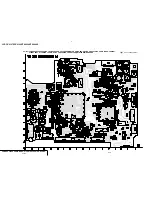
Страница 67: ...rn from the side which enables seeing The other layers patterns are not indicated Through hole is omitted Circled numbers refer to waveforms There are few cases that the part printed on diagram isn t mounted in this model Chip parts For schematic diagrams All capacitors are in µF unless otherwise noted p pF 50V or less are not indicated except for electrolytics and tantalums Chip resistors are 1 1...

Страница 68: ... 47u C2196 IC2191 V4 1 V3 2 V2 3 V1 4 N C 5 GND 6 CCD_OUT 7 VDD 8 DGND 9 SHT 10 VL 11 RG 12 H1 13 H2 14 R2191 10 0 1u F C2195 10k R2193 LND191 1 A CAM_15V 12V GND VSHT CAM_ 7 5V 5 0V GND CCD OUT V1 V2 V3 V4 GND RG H1 H2 BUFFER CCD IMAGER IC2191 IC2191 ICX437AK 43 ICX233AK 43 TO VC 272 BOARD 1 11 CN271 THROUGH THE FP 400 FLEXIBLE PAGE 4 35 CCD IMAGER XX MARK NO MOUNT CD 354 BOARD 7 G E F 4 6 B C 2 ...

Страница 69: ... 6 4 2 1 3 4 7 0 0 2 8 4 7 0 2 0 2 4 7 0 3 0 9 1 6 0 9 0 2 NO MARK REC PB MODE TH7701 6 8k TLSU1008 D7701 3 3k R7701 NSCW100 T38 D7702 33k R7705 UP04312008 Q7701 NJM2125F TE2 IC7701 1 2 3 4 5 0 5 33k R7703 0 5 22 R7706 3300 R7704 UP04601008 Q7702 0 5 180k R7702 6P CN7701 1 2 3 4 5 6 1 A VCC LED_ON OFF XTALLY_LED EVF_GND EVF_GND EVF_4 75V LED_DA BUFFER IC7701 LED DRIVE BACKLIGHT UNIT LED DRIVE THRO...

Страница 70: ... TG PRINTED WIRING BOARD Uses unleaded solder For printed wiring board Refer to page 4 61 for parts location This board consists of multiple layers However only the sides layers A and B are shown There are a few cases that the part printed on this diagram isn t mounted in this model ...

Страница 71: ...1 18 GND2 21 VG_DC_DET 19 VR_DC_DET 20 VR 22 VG 23 VB_DC_DET 24 VB 25 Vcc2 26 VP_DC_DET 27 VP 28 XVP SAVE 29 PFRP 30 FRP 31 PRG 32 BLACK_IN 33 BGP 34 N C 35 EXT_DA 36 R_INJECT 37 C_BG 38 XC SAVE 39 XSCK 40 SI 41 XCS 42 Vcc1 45 XP SAVE 44 LPF_ADJ 43 TRAP_ADJ 46 B_IN 47 G_IN 48 R_IN 1u B C2016 470k R2001 100k R2011 XX C2002 1M R2010 0 001u B C2012 FB2002 0uH FB2001 0uH D2001 1SV290 TPL3 18P CN2001 1...

Страница 72: ...33 4 15 4 16 YAW SENSOR PITCH SENSOR For printed wiring board Refer to page 4 61 for parts location This board consists of multiple layers However only the sides layers A and B are shown Chip parts Transistor There are a few cases that the part printed on this diagram isn t mounted in this model C B E ...

Страница 73: ...S TX SO 16P CN752 1 2 3 4 5 6 7 8 9 10 11 12 13 14 15 16 R751 XX 0uH FB756 XX FB753 XX FB754 XX R757 FB755 0 CL750 CL751 CL752 CL753 CL754 CL755 CL756 CL757 CL758 CL759 1 A LIA2 SEIDEN LIA1 Vref 1 GND A_4 75V REG_GND MIC_R VREF1 LIA2 Vref2 SIRCS_PWM NS_ON LIA1 D_2 8V VREF2 GND Vcc SE_GND XF_TALLY_LED MIC_L Vcc MIC_GND XSIRCS_SIG A_2 8V SE_GND PITCH SENSOR YAW SENSOR MIC901 TO VC 272 BOARD 11 11 NO...

Страница 74: ...B DRIVE TIMING GENERATOR LCD DRIVE BACKLIGHT DRIVE PD 156 For printed wiring board Refer to page 4 61 for parts location This board consists of multiple layers However only the sides layers A and B are shown Chip parts Transistor Diode There are a few cases that the part printed on this diagram isn t mounted in this model C B E 5 6 4 2 1 3 3 2 1 ...

Страница 75: ...CCD TRV107E TRV108E TRV208E TRV408E Uses unleaded solder RGB DRIVE TIMING GENERATOR LCD DRIVE BACKLIGHT DRIVE PD 156 4 21 ...

Страница 76: ...UT 11 VCO 12 N C 13 N C 14 N C 15 Vcc4 16 VSH 17 GND1 18 GND2 21 G_DC_DET 19 R_DC_DET 20 VR 22 VG 23 B_DC_DET 24 VB 25 Vcc2 26 Vcc3 27 COM_OUT 28 N C 29 COM_FRP 30 FRP 31 GND3 32 BLACK_IN 33 BGP 34 N C 35 EXT_DA1 36 R_INJECT 37 EXT_DA2 38 XC SAVE 39 XSCK 40 SI 41 XCS 42 Vcc1 45 XP SAVE 44 LPF_ADJ 43 TRAP_ADJ 46 B_IN 47 G_IN 48 R_IN 22k R5509 560p CH C5511 0 01u B C5531 XX C5522 XX C5508 TA C5528 1...

Страница 77: ...C 5 VLCD 6 VDD 7 SCK 8 SD 9 XCS 10 C XD 11 COM1 12 COM2 13 COM3 14 COM4 15 SEG1 16 SEG2 17 SEG3 18 SEG4 19 SEG5 20 SEG6 21 SEG7 22 SEG8 23 SEG9 24 SEG10 25 SEG11 26 SEG12 27 SEG13 28 SEG14 29 SEG15 30 SEG16 31 SEG17 32 SEG18 0 1u B C5701 CN5705 XX 1 2 3 4 CN5703 20P 1 2 3 4 5 6 7 8 9 10 11 12 13 14 15 16 17 18 19 20 680k R5704 ND901 D901 1 A REG_GND SE_GND SEG4 SEG15 SEG6 SEG11 COM1 COM1 SEG1 SEG1...

Страница 78: ... 1 2 3 4 5 6 7 8 9 10 11 12 13 14 S023 1 A1 3 A2 2 B1 4 B2 S001 CL001 CL002 CL003 CL004 CL005 CL006 CL007 CL008 1 A 22P 1 SP BEEP 2 SP 3 LI_3V 4 KEY_AD0 5 KEY_AD2 6 REG_GND 7 XHI_RESET 8 KEY_AD4 9 D_2 8V 10 KEY_AD3 11 DIAL_B 12 DIAL_A 13 KEY_AD2 14 D_2 8V 15 KEY_AD1 16 XCS_LCD_DRIVER 17 LCD_COM XDATA 18 OSD_SO 19 XOSD_SCK 20 EVER_3 0V 21 DISP_BL EL_BL 22 REG_GND DISPLAY TITLE EASY DUBBING END SEAR...

Страница 79: ...FP 299 FLEXIBLE 1 680 434 11 11 1 4 MR SENSOR C B A COM 1 677 049 2 1 3 4 5 6 7 8 9 10 11 12 13 14 15 1 2 3 4 1 2 3 4 S REEL SENSOR T REEL SENSOR H002 H001 TAPE TOP C TAPE END C TAPE LED K TAPE LED A GND S REEL S REEL SENSOR Vcc T REEL T REEL HALL COM ME MP REC PROOF Hi8 MP C LOCK SW FP 300 FLEXIBLE LS 057 BOARD FP 302 FLEXIBLE FP 301 FLEXIBLE Q002 TAPE END SENSOR D001 TAPE LED Q001 TAPE TOP SENSO...

Страница 80: ...MERA PROCESSOR AMP Y C PROCESSOR FOCUS ZOOM MOTOR DRIVE REC PB AMP LINE OUT AMP SERVO MODE CONTROL STEADY SHOT HI CONTROL AUDIO DC DC CONVERTER CONNECTOR PRINTED WIRING BOARD Uses unleaded solder CAMERA VIDEO SERVO MODE HI CONTROL AUDIO D D CONV VC 272 ...

Страница 81: ...D D CONV VC 272 For printed wiring board Refer to page 4 62 for parts location This board consists of multiple layers However only the sides layers A and B are shown Chip parts Transistor Diode There are a few cases that the part printed on this diagram isn t mounted in this model C B E 5 6 4 2 1 3 3 2 1 ...

Страница 82: ... AD10 AD8 AD7 AD6 AD5 AD4 AD3 AD2 AD1 ADCK A_2 8V 6 3V 10u C279 0 22u B C276 100k R274 C287 1u B C286 1u B FB275 0 01u B C277 0 1u B C281 0 1u B C289 B 0 1u C288 XX R279 CXD2444R T4 IC271 1 CLPDM 2 PBLK 3 VSS1 4 OSCI 5 OSCO 6 VSS2 7 CK 8 TEST 9 CHCK 10 VDD1 11 SYSCK 12 VICK CL 13 VDD2 14 VSS3 15 XSHP 16 XSHD 17 XRS 18 RG 19 VDD3 20 VDD4 21 H1 22 H2 23 VSS4 24 N C 25 V2 26 V1 27 VH 28 V3 29 VL 30 V...

Страница 83: ...LDO 142 MEMVDI 143 VIVDO 144 VINNAD 44 AVDD 52 VRTAD 43 Y_RF_IN 51 VRBAD 42 VREFOP 50 VDDAA0 41 ATF_IN 49 VDDAA1 40 C_IN 48 REXT1 39 VSSAA0 47 CBU1 38 OP_OUT 46 DAO1 37 AD_IN 45 MEMHDI 145 VIHDO 146 IO_VDD4 147 EN0 148 DIR0B 149 DIR0A 150 DIR1A 151 DIR1B 152 EN1 153 DVSS8 154 VCKO 155 TESTBS 156 XTECVRST 157 TBCVD 158 IRIS 159 TEST 160 SENS0 161 SENS1 162 DVDD4 163 VCK 164 DVSS9 165 XSG1 166 VGAT ...

Страница 84: ...9 1k R304 330 R319 1M R307 1k R321 HALL_REF DIR0B 2200 R313 ZM_RST 2200 R308 47k R301 0 22u B C309 EN1 DIR1A FC_RST LENS_FILTER_ON_SW 0 01u B C313 220k R310 DIR1B LENS_TEMP_AD 0 1u B C319 6 3V 10u A TA C304 1 16W 10 R306 A_4 75V ZM_RST_LED MPC17A135DTAEL IC301 1 VM 2 OUT 1A 3 PGND 4 OUT2A 5 OUT3A 6 PGND 7 OUT4A 8 VM4 9 IN1 10 EN1 11 IN2 12 EN2 13 IN3 14 EN3 15 IN4 16 EN4 17 OUT4B 18 PGND 19 OUT3B ...

Страница 85: ...116 0 1u B C113 27k R109 220uH L101 220 R110 220 R111 0 022u B C106 0 022u B C107 0 01u B C103 0 01u C101 6 3V 33u C102 B 0 01u C108 FB101 0uH FB102 0uH 27k R106 0 1u B C114 2700 R117 0 01u C117 0 01u C126 B 0 47u C134 Q107 RN2111F 0 01u B C104 0 01u B C131 0 01u B C133 0 01u B C125 RP_4 75V REG_GND VC_RF_SWP RP_PB_MODE BOTH_REC DOP PB_RF REC_2 REC_AFM PB_RF PB_C_RF PB_C_RF RF_AGC_OUT DOP REC_RF X...

Страница 86: ... 1 3 5 4 8 2uH L2304 470 R2314 RN4990FE Q2305 6 2 1 3 5 4 120p CH C2316 22u 4V C2322 2SC4738F Y Q2303 270 R2302 IC2301 BA7665FS E2 1 2 3 4 5 6 7 8 9 10 11 12 13 14 15 16 2SC4738F Y Q2302 8 2uH L2305 2 2u B C2319 HN1A01FE Y GR Q2301 6 2 1 3 5 4 270 R2301 VOUT_ON LINE_Y 10k R2320 RB2303 75x4 10u B 6 3V C2312 IC151_C_OUT 22p CH C2303 1u B C2317 120p CH C2315 120p CH C2305 C_I O 220 R2311 RB2302 2 2kx...

Страница 87: ... 9 10 11 12 13 14 15 16 17 18 19 20 21 22 23 24 25 26 27 28 29 30 31 32 33 34 35 36 37 38 39 40 41 42 43 44 45 46 47 48 49 50 51 52 53 54 55 56 57 58 59 60 61 62 63 64 0 1u B C462 0 1u B C492 0 1u B C491 CAP_ON XREC_PROF_SW HI8_MP_SW ME_SW CAP_FG 1 A REG_GND XLM_LIM_ON XCC_DOWN UNLOAD LOAD XLM_LIM_ON LM_LIM_CONT UNLOAD LOAD XLM_LIM_ON LM_LIM_CONT DRUM_PG_SENS FG_PG_COM FG_PG_COM DRUM_FG_SENS DRUM_...

Страница 88: ...MECHA_VD XCS_CH 0 1u B C408 LOAD FC_RST TAPE_LED_ON DRUM_PWM DRUM_PG UNLOAD 1u B C401 ZM_RST HI_SI XX R440 B 0 01u C410 R430 XX VC_SI B C407 0 01u IC801_PWCTRL AGC_SLOW 10p CH C404 TREEL_FG XREC_PROF_SW DRUM_START XHI_SCK CL401 10p CH C403 DA_STB DRUM_FG 27k R441 0 5 100k R442 CL2303 XCS_AU VC_SO XVC_SCK XRST_IC151 CK_CONT1 CK_CONT2 LCD_HOLD VC_SO XVC_SCK VC_SI VC_SO XVC_SCK IC901 NJM3230V TE2 PAS...

Страница 89: ...7 8 RB512 XX 1 2 3 4 5 6 7 8 RB511 470kx4 1 2 3 4 5 6 7 8 R559 33 2200 R561 1k R562 XS_JACK_IN USB_D PULLUP XX R507 XX R508 RB505 47kx4 1 2 3 4 5 6 7 8 Q502 RN1110F 1 2 3 VOUT_ON RB507 2200x4 1 2 3 4 5 6 7 8 RB508 1Mx4 1 2 3 4 5 6 7 8 RB509 220kx4 1 2 3 4 5 6 7 8 RB513 2200x4 1 2 3 4 5 6 7 8 MA132WK K8 SO D502 1 2 3 2200 R502 USB_DET LANC_IN RB514 100kx4 1 2 3 4 5 6 7 8 RN1904FE Q503 6 2 1 3 5 4 3...

Страница 90: ...64 100k SP XX R387 XX R391 FSC SP R363 8200 R353 XX 1u B C385 47k R382 0 01u C358 0 1u B C375 XX C356 150k R368 0 47u B C394 IC352 XX 1 2 3 4 5 470k R373 RN4990FE Q355 4V 22u C374 6 3V 22u C357 C376 XX 4 7u B C354 RP_IR MT_F0 HALL_REF A_2 8V A_4 75V XRF_AGC_OFF DOC_DET FRQ_TUNE 4 7u F C602 1u B C603 REC_BIAS HALL_OFFSET MT_Q FB601 0uH CFG_DUTY BH2222FV E2 IC601 1 2 3 4 5 6 7 8 9 10 11 12 13 14 15 ...

Страница 91: ...k R021 4 7uH L010 REG_GND TPCS8302 TE12L Q002 IC001 CXA3282R T6 1 2 3 4 5 6 7 8 9 10 11 12 13 14 15 16 17 18 19 20 21 22 23 24 25 26 27 28 29 30 31 32 33 34 35 36 37 38 39 40 41 42 43 44 45 46 47 48 49 50 51 52 53 54 55 56 57 58 59 60 61 62 63 64 22k R040 XN09D6100LS0 Q010 2 2u F C057 10u 6 3V C038 A REG_GND HN1C01FE Y GR TPLR3 Q014 6 2 1 3 5 4 4 7u 10V B C032 10u B C020 LND008 REG_GND VTR_UNREG D...

Страница 92: ...C_RF_SWP EVF_VG CAP_FG EVF_VG EVF_R EVF_B EVF_DD_ON A_2 8V Y_I O A_4 75V A_2 8V D_2 8V EP_13 3V EP_2 8V EVF_PANEL_4 75V PANEL_ 15 3V BL_REG VL_UNREG BL_CONT PB_RF REC_2 PANEL_SYNC LANC_OUT PANEL_B CAP_FG LCD_HOLD REC_AFM PANEL_G XCS_LCD_DA XLANC_POWER_ON VC_RF_SWP LANC_IN KEY_AD5 PANEL_R PANEL_XHD XVC_SCK EVF_DD_ON EVF_G BW_Y XSYS_RST XCS_EVF_DA VC_SO EVF_R PANEL_XVD EVF_VG EVF_B XTALLY_LED F_RATE...

Страница 93: ...P 397 FLEXIBLE FP 397 FLEXIBLE BOARD For printed wiring board There are a few cases that the part printed on this diagram isn t mounted in this model Y C G G J201 J202 S VIDEO OUT RFU DC OUT A V OUT FP 397 FLEXIBLE 1 20 1 683 160 21 VIDEO LIGHT ...

Страница 94: ... 0Vp p 19 0Vp p H 3 4Vp p 6 IC2191 q 7 IC2191 qdqf 1 IC2191 1 5 3Vp p H 17 5Vp p 20 msec 20 msec 105 nsec V 9 IC2002 rk 2H 2H 2H 91nsec VF 150 BOARD 2 IC2001 ws 1 IC2001 w 7 4Vp p 7 5Vp p 3 1Vp p 3 1Vp p 3 IC2001 wf 7 4Vp p 4 IC2001 rh H H H 0 4Vp p 5 IC2001 rj 0 4Vp p 7 IC2002 1 6 IC2001 rk H 2 2Vp p 8 IC2002 wh 0 4Vp p WAVEFORMS CD 354 VF 150 ...

Страница 95: ...0 IC272 ef PB 0 6Vp p H H H qa IC272 eh PB 50 nsec div 0 4Vp p H 460mVp p qs IC151 xzc REC PB 9 IC272 e REC 0 4Vp p H 34 9nsec 69 8nsec 105nsec 69 8nsec 20msec qf IC151 7 REC qg IC151 qf REC PB qh IC151 qj REC PB qd IC151 4 REC PB 460mVp p H VC 272 BOARD 2 IC271 qa REC PB 1 IC271 5 REC PB 2 8Vp p 3 8Vp p 1 9Vp p 5 3Vp p 3 IC271 waws REC 3 2Vp p 4 IC271 wg REC H 5 4Vp p 5 IC271 wh REC 20msec 17 5Vp...

Страница 96: ...c div 50 nsec div 50 nsec div 324nsec wl IC2301 7 REC PB 0 7Vp p H e IC2301 9 REC PB S C OUT H 1 5Vp p H 2Vp p es IC2301 qfqg REC PB S Y OUT wk IC2301 2 REC PB 1 0Vp p H H ea IC2301 qaqs REC PB 2Vp p ef IC402 rj REC PB ed IC402 1 REC PB 2 3Vp p 2 9Vp p eh IC451 ws REC PB eg IC451 qh REC PB ej IC451 wg REC PB ek IC451 wk REC PB el IC451 tj tl ya REC PB 1 3Vp p 5 6 msec 2 8Vp p 2 8Vp p 80mVp p 100mV...

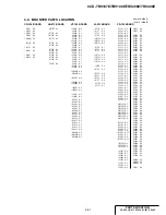
Страница 97: ...4 C5506 B 4 C5507 B 4 C5508 B 4 C5509 B 2 C5510 B 3 C5511 B 4 C5512 B 4 C5513 B 3 C5514 B 2 C5515 B 4 C5516 B 4 C5517 C 3 C5518 C 3 C5519 C 3 C5520 B 2 C5521 C 5 C5522 B 6 C5523 D 5 C5524 C 6 C5527 B 3 C5528 D 4 C5529 B 4 C5530 D 6 C5531 D 6 C5532 C 5 C5603 D 3 C5604 B 6 C5605 B 6 C5606 D 2 C5607 D 4 C5608 D 4 C5701 A 3 CN5501 D 5 CN5502 B 3 CN5601 D 2 CN5701 B 1 CN5702 A 1 CN5703 A 5 CN5704 A 2 C...

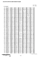
Страница 98: ...B 15 C464 A 7 C465 C 16 C466 C 15 C467 B 16 C468 C 15 C469 B 16 C470 C 15 C471 B 15 C472 C 15 C473 C 15 C475 C 15 C476 C 15 C477 B 15 C478 B 15 C479 B 15 C480 B 15 C481 B 14 C482 B 14 C483 B 15 C484 C 15 C485 B 16 C486 A 15 C487 A 15 C488 B 15 C489 A 15 C490 A 15 C491 A 15 C492 A 18 C501 D 12 C502 D 12 C503 D 7 C504 D 7 C505 D 6 C506 D 6 C507 D 6 C508 D 6 C509 D 6 C510 D 7 C511 D 7 C512 D 7 C513 B...

Страница 99: ... E 10 R716 E 7 R717 E 7 R718 E 7 R719 E 7 R720 E 6 R721 D 6 R722 E 7 R801 E 11 R802 E 10 R806 E 8 R811 D 8 R816 D 10 R817 C 11 R818 C 11 R819 C 11 R820 E 7 R905 B 17 R906 B 17 R907 A 17 R908 A 17 R909 A 17 R2301 E 2 R2302 E 1 R2307 C 18 R2310 D 1 R2311 D 1 R2312 D 1 R2313 D 1 R2314 D 1 R2315 D 2 R2316 D 1 R2317 D 1 R2318 D 1 R2319 D 1 R2320 D 1 R2321 D 1 RB001 E 8 RB101 B 5 RB102 B 4 RB151 B 3 RB2...

Страница 100: ...5 1 CCD TRV107E TRV108E TRV208E TRV408E SECTION 5 ADJUSTMENTS ...

Страница 101: ...o out VC 272 board IC601 EVR VC 272 board IC351 Audio process SI 033 board SE750 751 PITCH YAW sensor 3 PD 156 board IC5501 RGB driver LCD PD 156 board IC5502 Timing generator LCD VF 150 board IC2001 RGB driver EVF VF 150 board IC2002 Timing generator EVF LB 073 board D7702 Back light LED EVF Adjustment Section Initialization of D E F 7 page data Camera EVF LCD Servo Video Audio Mechanism Adjustme...

Страница 102: ...the video light reset the data of page 2 address E0 to E2 to 00 3 Steady shot model CCD TRV408E Adjustment Section Initialization of D E F 7 page data Camera EVF LCD Servo Video Audio Mechanism Adjustment Initialization of D E F 7 page data Modification of D E F 7 page data HALL adj Flange back adj Color reproduction adj AWB LV standard data input Auto white balance adj Steady shot check 3 RGB AMP...

Страница 103: ...082 384 A Usage Auto white balance adjustment check White balance adjustment check White balance check White balance check White balance check For checking the flange back For adjusting the LCD block For connecting the adjustment remote commander For adjusting the flange back For adjusting the flange back 5 1 CAMERA SECTION ADJUSTMENT 1 1 PREPARATIONS BEFORE ADJUSTMENT CAMERA SECTION 1 1 1 List of...

Страница 104: ... date time user set menus will be lost After completing adjustments reset these data If the cabinet R has been removed the self diagnosis data data on history of use total drum rotation time etc will be lost Before removing note down the self diagnosis data data of page 2 address B0 to C6 and data on history use data of page 2 address A2 to AA and E0 to E2 Refer to 5 4 Service Mode for the self di...

Страница 105: ... board CN752 A V OUT jack Must be connected when performing the EVF system adjustments To SS 2000 block DC IN jack AC power adaptor 8 4Vdc AC L10 or AC VQ800 etc AUDIO black AC power adaptor 8 4Vdc AC L10 or AC VQ800 etc Terminated at 75 Ω Vector scope Adjustment remote commander L series Info LITHIUM Battery 7 2Vdc Color monitor LANC jack CPC jig for SB J 6082 539 A Front panel block VIDEO Yellow...

Страница 106: ...roduction adjustment frame Remove the color bar chart from the pattern box and insert a clear chart in its place Do not perform zoom operations during this time 3 Flange back adjustment chart Make the chart shown in Fig 5 1 6 using A0 size 1189mm 841mm black and white vellum paper Fig 5 1 6 Note Use matte vellum paper bigger thanA0 and make sure the edges of the black and white paper joined togeth...

Страница 107: ... data built in the different model the camcorder may not operate 3 When changing the data press the PAUSE button of the adjustment remote commander each time when setting new data to write the data in the non volatile memory 4 Check that the data of adjustment addresses is the initial value If not change the data to the initial value Processing after Completing Modification of D E F 7 Page data Or...

Страница 108: ...D E F 7 Page Data Fixed data 2 Modified data Refer to 2 Modification of D E F 7 Page Data 00 to 0F 10 11 12 13 14 15 16 17 18 19 1A 1B 1C 1D 1E to 21 22 23 to 2F 30 31 32 33 34 35 36 37 38 39 3A 3B 3C to 3D 3E 3F 40 41 42 to 44 45 46 47 48 49 4A 4B 4C 4D 4E 4F 50 51 52 53 00 00 00 00 00 00 00 00 00 00 00 00 68 80 8D 80 7A 2B 80 65 80 8D 87 FB 33 C8 34 8C 28 07 3A 4A 12 0B 54 00 19 00 37 00 00 04 E...

Страница 109: ...fo adj Y OUT level adj C OUT level adj Fixed data 1 REC Y current adj Fixed data 1 REC C AFM current adj Fixed data 1 1 5MHz deviation adj BPF fo adj Fixed data 1 Fixed data 2 Fixed data 1 Fixed data 2 Fixed data 1 Fixed data 2 Fixed data 1 Fixed data 2 Fixed data 1 Fixed data 2 Fixed data 1 Color reproduction adj Fixed data 1 Fixed data 2 Fixed data 1 Fixed data 2 Fixed data 1 Fixed data 2 Modifi...

Страница 110: ... 44 45 46 47 48 49 4A 4B 4C to 53 54 55 56 to 6B A0 2F 6E 63 8E 29 C3 60 65 50 Fixed data 1 Fixed data 2 Fixed data 1 Fixed data 2 Modified data Copy the data built in the same model Fixed data 1 Fixed data 2 RGB AMP adj EVF Fixed data 1 Contrast adj EVF Fixed data 1 Fixed data 2 VCO adj LCD V COM adj LCD RGB AMP adj LCD Fixed data 1 COM AMP adj LCD White balance adj LCD Contrast adj LCD Fixed dat...

Страница 111: ...e 1 0 01 01 Set the data 2 6 94 88 Set the data 3 6 95 17 Set the data 4 6 01 6D Set the data and press PAUSE button 5 6 02 Check that the data changes to 01 Note2 6 6 01 00 Set the data and press PAUSE button Note2 The adjustment data will be automatically input to page F address 30 31 32 Checking method Order Page Address Data Procedure 1 0 03 03 Set the data 2 6 01 01 Set the data and press PAU...

Страница 112: ...n coincide Specified voltage The specified voltage varies according to the minipattern box so adjust the power supply output voltage to the specified voltage written on the sheet which is supplied with the minipattern box Adjusting method for 1 4 CCD model Order Page Address Data Procedure 1 0 01 01 Set the data 2 F 86 Write down the data 3 F 86 00 Set the data and press PAUSE button 4 6 01 13 Set...

Страница 113: ...turn on again 3 Perform Flange Back Adjustment 2 3 2 Flange Back Adjustment 2 Perform this adjustment after performing Flange BackAdjustment 1 Subject Subject more than 500m away Subjects with clear contrast such as buildings etc Measurement Point Check operation on TV monitor Measuring Instrument Adjustment Page F Adjustment Address 46 to 55 58 Note1 Check that the data of page 6 address 02 is 00...

Страница 114: ...n be checked if it is focused or not by observing the data on the page 1 of the adjustment remote commander 1 Select page 0 address 03 and set data 0F 2 Page 1 shows the state of the focus 1 00 XX Odd Focused Even Unfocused Switch setting NIGHT SHOT Lens block OFF Checking method 1 Select page 6 address 40 and set data 02 2 Select page 6 address 41 and set data 01 3 Place the Siemens star 2 0m fro...

Страница 115: ...data 3 Select page F address 77 set data 29 and press the PAUSE button 4 Select page F address 2B set data 97 and press the PAUSE button 5 Select page 6 address 01 set data 3D and press the PAUSE button 6 Adjust the GAIN and PHASE of the vectorscope and adjust the burst luminance point to the burst position of the color reproduction frame 7 Change the data of page F address 3F 41 AF and B0 settle ...

Страница 116: ...ot to page 6 address 01 set data 00 and press the PAUSE button Switch setting 1 NIGHT SHOT Lens block OFF 2 DIGITAL ZOOM Menu display OFF 3 STEADY SHOT Menu display OFF 4 LIGHT FK 2000 block OFF Adjusting method Order Page Address Data Procedure 1 0 01 01 Set the data 2 Wait for 2 sec 3 6 01 11 Set the data and press PAUSE button 4 6 01 0D Set the data and press PAUSE button 5 6 02 Check that the ...

Страница 117: ...ata 3 F 90 Write down the data 4 F 90 2B Set the data and press PAUSE button 5 F 91 Write down the data 6 F 91 Set the following data and press PAUSE button 00 1 6 CCD model 80 1 4 CCD model 7 F 92 Write down the data 8 F 92 Set the following data and press PAUSE button 61 1 6 CCD model 5E 1 4 CCD model 9 F 93 Write down the data 10 F 93 80 Set the data and press PAUSE button 11 6 01 A7 Set the da...

Страница 118: ...within the circle shown Fig 5 1 12 A 4 6 01 00 Set the data and press PAUSE button Outdoor white balance check 5 6 01 3F Set the data and press PAUSE button 6 Place the C14 filter on the lens 7 Check that the center of the white luminance point is within the circle shown Fig 5 1 12 B 8 Remove the C14 filter LV data check 9 Place the ND filter 1 5 1 0 0 1 0 4 on the lens 10 6 01 0F Set the data and...

Страница 119: ...rmed properly Subject Arbitrary Measurement Point Display data of page 1 Note Measuring Instrument Adjustment remote commander Specified Value 2700 to 5100 Note Displayed data of the adjustment remote commander 1 XX XX Display data Switch setting 1 STEADY SHOT Menu display ON 2 ZOOM TELE end Checking method Order Page Address Data Procedure Pitch sensor check SI 033 board SE750 1 0 03 11 Set the d...

Страница 120: ... for SB or connect the L series Info LITHIUM battery to the battery terminal of CPC jig for SB The following table shows the Pin No and signal name of CN713 Table 5 1 6 The following table shows the arrangement of the test points of CPC jig for SB Pin No are those of CN713 Table 5 1 7 Pin No 1 2 3 4 5 6 7 8 Signal Name N C IR VIDEO BPF MONI CAP FG RF SWP REG GND REC RF REG GND Pin No 9 10 11 12 13...

Страница 121: ... data and press PAUSE button 3 6 02 Check that the data changes from 00 to 01 4 6 01 00 Set the data and press PAUSE button 5 0 01 00 Set the data 1 2 Manual Adjustment Mode Camera Subject Arbitrary Measurement Point EVF VG Pin qf of CN713 of VC 272 board Measuring Instrument Oscilloscope Adjustment Page 7 Adjustment Address 36 Specified Value A 7 22 0 27V Adjusting method Order Page Address Data ...

Страница 122: ... and press PAUSE button 3 6 02 Check that the data changes from 00 to 01 4 6 01 00 Set the data and press PAUSE button 5 0 01 00 Set the data 2 2 Manual Adjustment Mode Camera Subject Arbitrary Measurement Point EVF VG Pin qf of CN713 of VC 272 board Measuring Instrument Oscilloscope Adjustment Page 7 Adjustment Address 3A Specified Value A 2 28 0 12V Adjusting method Order Page Address Data Proce...

Страница 123: ...g J 6082 311 A The following table shows the Pin No and signal name of CN5502 Table 5 1 8 1 VCO Adjustment PD 156 board Set the VCO free run frequency If deviated the LCD screen will be blurred Mode VTR stop Signal No signal Measurement Point Pin 8 of CN5502 XHD OUT Measuring Instrument Frequency counter Adjustment Page 7 Adjustment Address 43 44 Specified Value f 15625 30Hz Adjusting method Order...

Страница 124: ...edestal to the specified value The data should be 00 to 3F 3 7 46 Press PAUSE button 4 0 01 00 Set the data Fig 5 1 16 Pedestal Pedestal A 2H 3 Contrast Adjustment PD 156 board Set the level of theVIDEO signal for driving the LCD to the specified value If deviated the screen image will be blackish or saturated whitish Mode VTR stop Signal No signal Measurement Point Pin 3 of CN5502 VG External tri...

Страница 125: ...ectrode drive signal of LCD to the specified value If deviated the LCD display will move producing flicker and conspicuous vertical lines Mode VTR stop Signal No signal Measurement Point Check on LCD display Measuring Instrument Adjustment Page 7 Adjustment Address 45 Specified Value The brightness difference between the section A and section B is minimum Note This adjustment should be carried out...

Страница 126: ...lacing the following parts If necessary adjust them 1 LCD panel 2 Light induction plate 3 IC5501 Adjusting method Order Page Address Data Procedure 1 0 01 01 Set the data 2 7 49 60 Set the data and press PAUSE button 3 7 4A 65 Set the data and press PAUSE button 4 7 49 Check that the LCD screen is not colored If not colored proceed to step 10 5 7 49 Change the data so that the LCD screen is not co...

Страница 127: ...s 1 Select page 0 address 01 and set data 01 2 Select page F address 20 set data 00 and press the PAUSE button of the adjustment remote commander 3 Select page D address 10 set data 00 and press the PAUSE button of the adjustment remote commander 4 Select page 0 address 01 and set data 00 5 Disconnect the power supply of the unit 2 3 TAPE PATH ADJUSTMENT 1 Preparations for Adjustment 1 Clean the t...

Страница 128: ...rtion meter 9 Audio attenuator 10 Regulated power supply 11 PAL alignment tapes For tracking adjustment WR5 1CP Parts code 8 967 995 07 For video frequency characteristics adjustment WR5 7CE Parts code 8 967 995 18 For checking Standard 8 mode operations For LP WR5 4CL Parts code 8 967 995 56 For SP WR5 5CSP Parts code 8 967 995 47 Note The following alignment tapes can also be used 1 WR5 3CL 8 96...

Страница 129: ...abinet R assembly disconnect the following connectors Note4 1 VC 272 board CN709 22P 0 5mm 2 VC 272 board CN701 20P 0 8mm 6 The lens block CD 354 board need not be connected To remove disconnect the following connectors 1 VC 272 board CN271 14P 0 5mm 2 VC 272 board CN301 24P 0 5mm 7 The EVF block VF 150 board need not be connected To remove disconnect the following connectors VC 272 board CN705 20...

Страница 130: ...able shows the arrangement of the test points of CPC jig for SB Pin No are those of CN713 Table 5 3 2 3 1 4 Connecting the Equipment Connect the measuring instruments as shown in Fig 5 3 2 and perform the adjustments Adjustment remote commander LANC jack Main unit A V OUT jack TV monitor VIDEO Yellow AUDIO Black Pin No 1 2 3 4 5 6 7 8 Signal Name N C IR VIDEO BPF MONI CAP FG RF SWP REG GND REC RF ...

Страница 131: ... minijack 1Vp p 75Ω unbalanced sync negative S video output 4 pin mini DIN Luminance signal 1Vp p 75Ω unbalanced sync negative Chrominance signal 0 300Vp p 75Ω unbalanced Audio output Stereo minijack 7 5dBs at load impedance 47kΩ impedance less than 2 2kΩ 3 1 7 Recording Mode Standard 8 Hi8 switching The record mode Standard 8 Hi8 of this unit switches as shown in the following table The playback ...

Страница 132: ...data and press PAUSE button 5 Check that Duty of CAP FG signal satisfies the specified value If not repeat steps 2 to 5 6 0 01 00 Set the data 2 Switching Position Adjustment VC 272 board If deviated in this case causes switching noise or jitter on the played back screen Mode Playback Signal Alignment tape For tracking adjustment WR5 1CP Measurement Point CH1 SWP Pin 5 of CN713 CH2 PB RF Pin 9 of ...

Страница 133: ...1 Set the data and press PAUSE button 4 F 45 Change the data and set the frequency f to the specified value 5 F 45 Press PAUSE button 6 2 01 00 Set the data and press PAUSE button 7 6 61 10 Set the data 8 0 01 00 Set the data 2 AFC f0 Adjustment VC 272 board Adjust the pull in range of theA D converted clock generator during playback Mode VTR stop Signal No signal Adjustment Page F Adjustment Addr...

Страница 134: ...SE button 6 2 01 00 Set the data and press PAUSE button 7 6 61 10 Set the data 8 0 01 00 Set the data 4 C OUT Level Adjustment VC 272 board Set the chroma signal output level Adjust the D A converter out put level of IC151 Mode VTR stop Signal No signal Measurement Point Chroma signal terminal of S VIDEO terminal 75Ω terminated Measuring Instrument Oscilloscope Adjustment Page F Adjustment Address...

Страница 135: ...n the data 6 D 15 6F Set the data and press PAUSE button 7 Set to VTR recording mode Note3 8 E 9F Write down the data 9 E 9F 06 Set the data and press PAUSE button 10 F 69 Write down the data 11 F 69 00 Set the data and press PAUSE button 12 2 01 41 Set the data and press PAUSE button 13 6 63 01 Set the data 14 F 63 Change the data and set theY signal level A to the specified value 15 F 63 Press P...

Страница 136: ...f CN713 Measuring Instrument Oscilloscope 20 MHz BW LIMIT OFF Specified Value A 54 0 3 0mV Note1 Insert a plug into the S VIDEO or the A V jack Adjusting method Order Page Address Data Procedure 1 Insert a tape and set to VTR recording mode Note2 2 0 01 01 Set the data 3 2 01 41 Set the data and press PAUSE button 4 6 61 30 Set the data 5 E 9F Write down the data 6 E 9F 05 Set the data and press P...

Страница 137: ...to recording mode Note3 2 0 01 01 Set the data 3 2 01 41 Set the data and press PAUSE button 4 E 9F Write down the data 5 E 9F 07 Set the data and press PAUSE button 6 F 69 Change the data and set the REC AFM signal level A to the specified value 7 F 69 Press PAUSE button 8 E 9F Set the data written down at step 4 and press PAUSE button 9 2 01 00 Set the data and press PAUSE button 10 0 01 00 Set ...

Страница 138: ... and set the 400Hz audio signal level to the specified value 3 F 73 Press PAUSE button 4 0 01 00 Set the data 2 BPF f0 Adjustment VC 272 board Sets the BPF passing frequency of IC351 so that the AFM signal can separate from the playback RF signal properly If deviated the mono stereo mode will be differentiated incorrectly and noises and distortions will increase during high volume playback Mode Pl...

Страница 139: ...en the EDIT SEARCH button is pressed and decreases when the EDIT SEARCH button is pressed There are altogether 16 pages from 0 to F Changing the address The address increases when the FF M button is pressed and decreases when the REW m button is pressed There are altogether 256 addresses from 00 to FF Changing the data Data setting The data increases when the PLAY N button is pressed and decreases...

Страница 140: ...7 78 79 80 81 82 83 84 85 86 87 88 89 90 91 92 93 94 95 96 97 98 99 100 101 102 103 104 105 106 107 108 109 110 111 112 113 114 115 116 117 118 119 120 121 122 123 124 125 126 127 128 129 130 131 132 133 134 135 136 137 138 139 140 141 142 143 144 145 146 147 148 149 150 151 152 153 154 155 156 157 158 174 159 175 160 161 162 163 164 165 166 167 168 169 170 171 172 173 177 176 178 179 180 181 182 ...

Страница 141: ... of page D and F Page F Address 20 Data Function 00 Normal 01 Test mode Various emergency prohibitions and releases Drum emergency capstan emergency loading motor emergency reel emergency tape top and end DEW detection Page D Address 10 Data Function 00 Normal 01 Camera power ON 02 VTR power ON 03 Camera VTR power ON For page D and F the data set will be recorded in the nonvolatile memory by press...

Страница 142: ...gency The data corresponding to the emergency occurring the last will be written in the address 18 to 1B for this last emergency Therefore the data of addresses 18 to 1B are renewed each time an emergency occurs Note After completing adjustments be sure to initialize the data of address 10 to 1B to 00 Initializing method Order Page Address Data Procedure 1 0 01 01 Set the data 2 6 00 9F Set the da...

Страница 143: ...ssed Pinch roller is detached EJECT BL USE LOAD BL REW BL BL REC PB BL TURN BL STOP Loading Contents Position at which the cassette compartment lock is released The mechanism will not move any further in the unloading direction BLANC code Between two codes The mechanism will not be stopped by this code while it is operating EJECT completion position When the cassette is ejected the mechanism will ...

Страница 144: ... 1 1 1 0 0 0 0 1 1 1 1 bit1 or bit5 0 0 1 1 0 0 1 1 0 0 1 1 0 0 1 1 bit0 or bit4 0 1 0 1 0 1 0 1 0 1 0 1 0 1 0 1 A B 4 Switch check 1 Page 2 Address 43 Using method 1 Select page 2 address 43 2 By discriminating the bit value of display data the state of the switch can be discriminated 5 Switch check 2 Page 2 Address 49 Using method 1 Select page 2 address 49 2 By discriminating the bit value of d...

Страница 145: ...22 COUNTER RESET CF 2000 S017 BACK LIGHT CF 2000 S016 Data AB to D7 PANEL CLOSE CF 2000 S001 EXEC CF 2000 S019 FOCUS CF 2000 S018 D8 to FF No key input No key input PANEL OPEN CF 2000 S001 No key input No key input PANEL NORMAL PR 1000 Bit A2 A3 A4 A5 A6 A7 A8 A9 AA E0 E1 E2 Function Drum rotation Hour H counted time Hour L BCD code Minute User initial power Year on date Month BCD code Day Final c...

Страница 146: ...de Occurred 3rd time BC Repaired by code Occurred 4th time 1 BD Block function code Occurred 4th time BE Detailed code Occurred 4th time C0 Repaired by code Occurred 5th time 1 C1 Block function code Occurred 5th time C2 Detailed code Occurred 5th time C4 Repaired by code Occurred the last time 1 C5 Block function code Occurred the last time C6 Detailed code Occurred the last time 1 01 t C 03 t E ...

Страница 147: ...ce only with part number specified 1 3 067 347 01 MI SCREW M2 H 2 3 072 155 01 PLATE 20 MAGNIFICATION TRV208E TRV408E 2 3 072 155 11 PLATE 20 MAGNIFICATION TRV108E 2 3 072 155 21 PLATE 20 MAGNIFICATION TRV107E 3 X 3949 376 1 CAP N ASSY LENS 4 3 072 149 01 COVER 20 JACK 5 X 3952 094 1 CABINET L 20 ASSY 6 3 052 815 01 BELT ES GRIP 6 1 1 OVERALL SECTION Ref No Part No Description Remarks Ref No Part ...

Страница 148: ...TE 58 3 072 180 01 RETAINER REAR 20 MICROPHONE Ref No Part No Description Remarks Ref No Part No Description Remarks 59 3 072 179 01 RETAINER FRONT 20 MICROPHONE D750 8 719 060 65 DIODE DAC3825 D752 8 719 078 33 DIODE BR2222S 71 B2 IC750 6 701 681 01 IC RPM7140 V4 TRV107E TRV208E TRV408E MIC901 1 542 312 11 MICROPHONE SE750 1 803 042 31 SENSOR ANGULAR VELOCITY PITCH TRV408E SE751 1 803 042 41 SENS...

Страница 149: ...0 MD 113 1 476 978 11 SWITCH BLOCK CONTROL SS 2000 114 3 065 654 01 SHIELD 10 DD 115 A 7028 969 A VC 272 P V BOARD COMPLETE SERVICE TRV107E TRV108E TRV208E 115 A 7028 971 A VC 272 P VM BOARD COMPLETE SERVICE TRV408E 116 4 974 725 01 SCREW M1 7X2 5 P 117 3 072 147 01 CASE 20 SHIELD RP 118 1 683 595 11 FP 418 FLEXIBLE BOARD Ref No Part No Description Remarks Ref No Part No Description Remarks VC 272...

Страница 150: ...05 01 LID 20 JACK 157 3 072 202 01 PLATE 20 GROUND VF 158 3 072 203 01 KNOB 20 BATTERY RELEASE 159 3 968 771 01 SPRING COMPRESSION 160 3 072 204 01 LOCK 20 BATTERY 161 3 968 768 01 SPRING LOCK 162 3 968 770 01 SHAFT BT 163 3 072 207 01 SHEET METAL 20 LOWER STRAP BT901 1 694 772 11 TERMINAL BOARD BATTERY Ref No Part No Description Remarks Ref No Part No Description Remarks 151 152 152 152 153 154 1...

Страница 151: ...ABINET LOWER 20 ASSY EVF 210 1 683 164 11 FP 401 FLEXIBLE BOARD 211 A 7078 025 A VF 150 BW BOARD COMPLETE 212 A 7078 026 A LB 073 BW BOARD COMPLETE 213 3 072 214 01 GUIDE 20 LAMP 214 3 072 211 01 ILLUMINATOR 215 3 072 210 01 SHEET PRISM 216 3 072 194 01 CABINET UPPER 20 EVF 217 X 3951 168 1 LENS B ASSY VF 218 X 3952 107 1 CABINET REAR 20 ASSY EVF LCD903 8 753 028 49 LCX032AP J Ref No Part No Descr...

Страница 152: ...054 11 RUBBER FM SHIELD TRV107E TRV108E TRV208E 257 A 7078 035 A CD 354 BOARD COMPLETE 258 3 318 203 11 SCREW B1 7X6 TAPPING IC2191 A 7012 087 A CCD BLOCK ASSY CCD IMAGER TRV107E TRV108E TRV208E IC2191 A 7031 049 A CCD BLOCK ASSY CCD IMAGER TRV408E M905 1 763 796 11 MOTOR STEPPING F631B FOCUS M906 1 763 046 21 MOTOR STEPPING Z600 ZOOM Ref No Part No Description Remarks Ref No Part No Description R...

Страница 153: ... WINDOW 21 LCD TRV408E 320 3 072 152 41 WINDOW 21 LCD TRV208E 320 3 072 152 51 WINDOW 21 LCD TRV107E 320 3 072 152 71 WINDOW 21 LCD TRV108E 321 3 959 978 02 CUSHION PANEL 322 3 941 343 21 TAPE A LCD901 1 803 852 31 INDICATOR MODULE LIQUID CRYSTAL LCD902 A 7028 734 A INDICATION LCD BLOCK ASSY H 0ND901 1 518 796 11 TUBE FLUORESCENT COLD CATHODE Ref No Part No Description Remarks Ref No Part No Descr...

Страница 154: ...SSY R DRIVE 707 3 065 840 01 CUT 0 98X3X0 13 LUMILER W 708 3 065 935 01 HLC CUT 1 8X4X0 5 709 3 947 503 01 SCREW M1 4 710 X 3951 299 1 SCREW ASSY DRUM FITTING 711 3 074 309 01 ROLLER A LS GUIDE 712 7 624 101 04 STOP RING 1 2 E TYPE M901 A 7048 966 A DRUM DGH 0F4A R Ref No Part No Description Remarks Ref No Part No Description Remarks 711 701 704 701 703 707 708 709 706 702 705 710 M901 LS chassis ...

Страница 155: ... 01 SPRING TG1 ARM 774 3 065 821 01 RAIL T GUIDE 775 X 3951 289 1 TABLE S ASSY REEL 776 3 065 833 01 GUIDE LOCK 777 3 065 831 01 PLATE SPR RE RETURN 778 X 3951 304 1 ARM ASSY TG1 779 3 065 835 01 GUIDE S CASSETTE 780 3 065 820 01 SPRING RVS ARM 781 X 3951 296 1 BAND ASSY BT 782 3 065 836 01 COVER LS GREASE 783 3 067 167 01 SCREW M1 4X2 CAMERA TAPPING D001 8 719 988 42 DIODE GL453 TAPE LED H001 8 7...

Страница 156: ...Description Remarks Ref No Part No Description Remarks 6 1 10 MECHANICAL CHASSIS BLOCK ASSEMBLY 1 805 810 802 809 802 815 824 817 819 802 823 820 821 822 815 818 816 811 805 807 815 814 813 812 806 801 803 804 808 M902 M903 Mechanical chassis block assembly 2 See page 6 11 not supplied 814 3 065 881 01 SPRING P PRESSURE PLATE 815 3 065 934 01 HLW CUT 0 98X3X0 25 816 1 786 096 11 SWITCH ROTARY 817 ...

Страница 157: ...854 3 065 917 01 GEAR 1 CAM RELAY 855 3 065 934 01 HLW CUT 0 98X3X0 25 856 3 065 915 01 GEAR 1 CAM 857 3 065 878 01 PLATE S GUIDE LOCK 858 3 065 932 01 PAN 2 MAIN M1 4X1 6 CAMERA 859 A 7096 413 A GEAR S ASSY GUIDE 860 7 624 101 04 STOP RING 1 2 E TYPE 861 A 7096 412 A GEAR T ASSY GUIDE 862 X 3951 307 1 PLATE ASSY M SLIDE 863 X 3951 305 1 ARM ASSY LS 864 3 065 901 01 ROLLER LS ARM 865 3 065 916 01 ...

Страница 158: ...ES CHIP 10 5 1 16W R2193 1 218 965 11 RES CHIP 10K 5 1 16W A 7078 026 A LB 073 BW BOARD COMPLETE CONNECTOR CN7701 1 764 516 21 CONNECTOR FFC FPC ZIF 6P DIODE D7701 8 719 070 91 DIODE TLSU1008 T05 SOY 0D7702 8 719 082 33 DIODE NSCW100 T38 IC IC7701 8 759 581 11 IC NJM2125F TE2 TRANSISTOR Q7701 8 729 054 48 TRANSISTOR RN4983FE TPLR3 Q7701 8 729 054 45 TRANSISTOR UP04312008S0 Q7702 8 729 054 48 TRANS...

Страница 159: ...1 208 935 11 METAL CHIP 100K 0 5 1 16W R5505 1 218 967 11 RES CHIP 15K 5 1 16W R5506 1 218 958 11 RES CHIP 2 7K 5 1 16W R5507 1 218 973 11 RES CHIP 47K 5 1 16W R5508 1 218 975 11 RES CHIP 68K 5 1 16W R5509 1 218 969 11 RES CHIP 22K 5 1 16W R5510 1 218 975 11 RES CHIP 68K 5 1 16W R5511 1 218 989 11 RES CHIP 1M 5 1 16W R5512 1 218 977 11 RES CHIP 100K 5 1 16W R5513 1 218 989 11 RES CHIP 1M 5 1 16W R...

Страница 160: ...NTAL CHIP 22uF 20 6 3V C041 1 125 837 91 CERAMIC CHIP 1uF 10 6 3V C042 1 164 506 11 CERAMIC CHIP 4 7uF 16V C043 1 164 506 11 CERAMIC CHIP 4 7uF 16V C045 1 119 749 11 TANTAL CHIP 33uF 20 4V C046 1 119 750 11 TANTAL CHIP 22uF 20 6 3V C047 1 164 505 11 CERAMIC CHIP 2 2uF 16V C048 1 164 156 11 CERAMIC CHIP 0 1uF 25V C049 1 115 566 11 CERAMIC CHIP 4 7uF 10 10V C050 1 125 838 11 CERAMIC CHIP 2 2uF 10 6 ...

Страница 161: ...1 CERAMIC CHIP 0 1uF 10 10V C297 1 104 847 11 TANTAL CHIP 22uF 20 4V C302 1 164 943 11 CERAMIC CHIP 0 01uF 10 16V C303 1 164 941 11 CERAMIC CHIP 0 0047uF 10 16V C304 1 127 688 21 TANTAL CHIP 10uF 20 6 3V C304 1 135 259 11 TANTAL CHIP 10uF 20 6 3V C305 1 125 777 11 CERAMIC CHIP 0 1uF 10 10V C306 1 125 777 11 CERAMIC CHIP 0 1uF 10 10V C307 1 164 935 11 CERAMIC CHIP 470PF 10 50V C308 1 164 943 11 CER...

Страница 162: ...22uF 10 16V C514 1 164 942 11 CERAMIC CHIP 0 0068uF 10 16V C515 1 164 858 11 CERAMIC CHIP 22PF 5 50V C516 1 164 856 81 CERAMIC CHIP 18PF 5 50V C517 1 125 777 11 CERAMIC CHIP 0 1uF 10 10V C518 1 125 777 11 CERAMIC CHIP 0 1uF 10 10V C602 1 117 720 11 CERAMIC CHIP 4 7uF 10V C603 1 125 837 91 CERAMIC CHIP 1uF 10 6 3V C701 1 135 639 11 ELECT CHIP 47uF 20 6 3V C708 1 115 566 11 CERAMIC CHIP 4 7uF 10 10V...

Страница 163: ...1 8 759 489 19 IC uPC6756GR 8JG E2 TRV408E IC2301 8 759 662 95 IC BA7665FS E2 COIL L001 1 419 354 21 INDUCTOR 22uH L002 1 416 670 11 INDUCTOR 33uH L003 1 412 056 11 INDUCTOR 4 7uH L004 1 419 354 21 INDUCTOR 22uH L005 1 419 354 21 INDUCTOR 22uH L006 1 416 670 11 INDUCTOR 33uH L007 1 419 354 21 INDUCTOR 22uH L008 1 469 524 91 INDUCTOR 4 7uH L009 1 469 524 91 INDUCTOR 4 7uH L010 1 469 524 91 INDUCTOR...

Страница 164: ...1 16W R018 1 218 963 11 RES CHIP 6 8K 5 1 16W R020 1 218 965 11 RES CHIP 10K 5 1 16W R021 1 218 969 11 RES CHIP 22K 5 1 16W R023 1 218 971 11 RES CHIP 33K 5 1 16W R025 1 218 973 11 RES CHIP 47K 5 1 16W R026 1 218 969 11 RES CHIP 22K 5 1 16W R027 1 218 965 11 RES CHIP 10K 5 1 16W R029 1 218 961 11 RES CHIP 4 7K 5 1 16W R031 1 218 973 11 RES CHIP 47K 5 1 16W R032 1 218 969 11 RES CHIP 22K 5 1 16W R0...

Страница 165: ...18 1 218 953 11 RES CHIP 1K 5 1 16W R319 1 218 947 11 RES CHIP 330 5 1 16W R321 1 218 953 11 RES CHIP 1K 5 1 16W R322 1 218 965 11 RES CHIP 10K 5 1 16W R323 1 218 973 11 RES CHIP 47K 5 1 16W R351 1 218 953 11 RES CHIP 1K 5 1 16W R356 1 218 990 11 SHORT 0 R363 1 218 964 11 RES CHIP 8 2K 5 1 16W R364 1 218 977 11 RES CHIP 100K 5 1 16W R368 1 218 979 11 RES CHIP 150K 5 1 16W R372 1 218 973 11 RES CHI...

Страница 166: ...ES NETWORK 100KX4 1005 RB409 1 234 381 21 RES NETWORK 100KX4 1005 RB451 1 234 381 21 RES NETWORK 100KX4 1005 RB452 1 234 378 21 RES NETWORK 10KX4 1005 RB501 1 234 375 21 RES NETWORK 1KX4 1005 RB502 1 234 383 21 RES NETWORK 470KX4 1005 RB503 1 234 383 21 RES NETWORK 470KX4 1005 RB504 1 234 375 21 RES NETWORK 1KX4 1005 RB505 1 234 380 21 RES NETWORK 47KX4 1005 RB507 1 234 376 21 RES NETWORK 2 2KX4 1...

Страница 167: ...P2 EE NE RU UK 0 1 690 827 11 CORD SET POWER TRV108E TRV208E TRV408E AEP1 AEP2 EE NE RU 0 1 696 819 21 CORD POWER TRV107E AUS TRV408E AUS 0 1 769 608 11 CORD POWER TRV107E E TRV408E E 0 1 775 843 52 CORD POWER WITH FILTER TRV108E UK TRV208E UK TRV408E UK 0 1 782 476 11 CORD POWER TRV107E CH 0 1 783 374 11 CORD POWER TRV107E HK TRV408E HK 1 783 738 11 CORD CONNECTION AV CABLE 1 5m 0 1 790 732 11 CO...

Страница 168: ... Take a copy of CAMERA COLOR REPRODUCTION FRAME with a clear sheet for use 215 FOR CAMERA COLOR REPRODUCTION ADJUSTMENT CCD TRV107E TRV108E TRV208E TRV408E ...

Страница 169: ...CCD TRV107E TRV108E TRV208E TRV408E 216 Sony EMCS Co 2001L1600 1 2001 12 Published by DI Customer Center 9 929 927 11 ...

Страница 170: ...Revision History Ver 1 0 Date 2001 12 History Official Release Contents S M Rev issued 992992711 pdf Reverse ...

Отзывы: