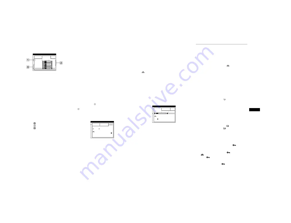
background image

1-6


14


EXPERT mode


You can make additional adjustments to the color in greater detail 
by selecting the EXPERT mode.


1


Move the joystick up or down to select the color 
temperature row 


1


. Then move the joystick left or 

right to select a color temperature.


2


Move the joystick up or down to select the 
adjustment item 


2


. Then move joystick left or right 

to adjust the BIAS (black level).


This adjusts the dark areas of an image.


3


Move the joystick up or down to select the 
adjustment item 


3


. Then move the joystick left or 

right to adjust the GAIN (white level).


This adjusts the light areas of an image.

You can adjust the R (red), G (green), B (blue) component of 
the input signal when making changes to items 


2


 and 


3


.

If you fine tune the color temperature, the new color settings 
are stored in memory for each of the three color temperatures 
and item 


1


 of the on-screen menu change as follows.

• [5000K]


t


[

1]

• [6500K]


t


[

2]

• [9300K]


t


[

3]


Setting the color temperature for each of the 
video input connectors


You can set the fine tuning of the color temperature in EASY or 
EXPERT mode for each of the video input connectors (HD15 and 
BNC).


1


Select the same adjustment mode and color 
temperature in the COLOR menu for both HD15 and 
BNC.


2


Fine tune the color temperature in each menu for 
HD15 and BNC.


The settings are stored in memory for each of the HD15 and 
BNC connectors.

For information on how to select the connector, see page 9.


sRGB mode


The sRGB color setting is an industry standard color space 
protocol designed to correlate the displayed and printed colors of 
sRGB compliant computer products. To adjust the colors to the 
sRGB profile, simply select the sRGB mode in the COLOR menu. 
However, in order to display the sRGB colors correctly (


γ


=2.2, 

6500K), you must set your computer to the sRGB profile and 
adjust the brightness (

) and contrast (


6


) to the numbers shown 

in the menu. For information on how to change the brightness 
(

) and contrast (


6


), see page 11.


Note


Your computer and other connected products (such as a printer), must be 
sRGB compliant.

EASY

EXPERT

s

B

G

R

5 0 0 0 K

6 5 0 0 K

9 3 0 K

0

R B I AS

0

5

G B I AS

0

5

B B I AS

0

5

R GA I N

0

5

G GA I N

0

5

B GA I N

0

5

CO LOR

EASY

EXPERT

s

B

G

R

: 5 6

: 7 6

FOR

s

B

G

R

I MAGE

RES TORA T I ON

ON

CO LOR


15

US


Restoring the color from the EASY or sRGB menus


The colors of most display monitors tend to gradually lose brilliance 
over several years of service. The IMAGE RESTORATION feature 
found in the EASY and sRGB menus allows you to restore the color 
to the original factory quality levels. The explanation below 
explains how to restore the monitor’s color from the EASY menu.


1


Move the joystick left or right to select EASY or 
sRGB mode.


2


First move the joystick up or down to select 

 (IMAGE RESTORATION). Then move the 

joystick to the right.


The picture disappears while the color is being restored (about 
2 seconds). After the color is restored, the picture reappears 
on the screen again.


Notes


• Before using this feature, the monitor must be in normal operation 

mode (green power indicator on) for at least 30 minutes. If the monitor 
goes into power saving mode, you must return the monitor to normal 
operation mode and wait for 30 minutes for the monitor to be ready. 
You may need to adjust your computer’s power saving settings to keep 
the monitor in normal operation mode for the full 30 minutes. If the 
monitor is not ready, the following message will appear.

• The monitor may gradually lose its ability to perform this function due 

to the natural aging of the picture tube.


Additional settings (OPTION)


You can manually degauss (demagnetize) the monitor, change the 
menu position, and lock the controls.


1


Press the joystick.


The main MENU appears on the screen.


2


Move the joystick to highlight 

 OPTION and press 

the joystick again.


The OPTION menu appears on the screen.


3


Move the joystick up or down to select the desired 
adjustment item.


Adjust the selected item according to the following 
instructions.


Degaussing the screen


The monitor is automatically demagnetized (degaussed) when the 
power is turned on.


To manually degauss the monitor, first move the 
joystick up or down to select 

 (DEGAUSS). Then 

move the joystick to the right.


The screen is degaussed for about 2 seconds. If a second degauss 
cycle is needed, allow a minimum interval of 20 minutes for the 
best result.


Changing the menu’s position


Change the menu’s position if it is blocking an image on the 
screen.


To change the menu’s on-screen position, first move 
the joystick up or down to select 

 (OSD H POSITION) 

for horizontal adjustment, or 

 (OSD V POSITION) for 

vertical adjustment. Then move the joystick left or right 
to shift the on-screen menu.


Locking the controls


To protect adjustment data by locking the controls, first 
move the joystick up or down to select 

 (CONTROL 

LOCK). Then move the joystick to the right, to select 
ON.


Only the 


1


 (power) switch, EXIT, and 

 (CONTROL LOCK) 

of the 

 OPTION menu will operate. If any other items are 

selected, the 

 mark appears on the screen.


To cancel the control lock


Repeat the procedure above and set 

 (CONTROL LOCK) to OFF.

EASY

EXPERT

s

B

G

R

5 0 0 0 K

6 5 0 0 K

9 3 0 K

0

5 0

K

0

0

I MAGE

RES TORA T I ON

AVA I L AB L E
A F T ER WARM UP

CO LOR

Содержание FD Trinitron GDM-F500R

Страница 1: ... 3 µsec Vertical blanking width should be more than 450 µsec If the input signal is Generalized Timing Formula GTF compliant the GTF feature of the monitor will automatically provide an optimal image for the screen Design and specifications are subject to change without notice CRT 0 22 mm aperture grille pitch 21 inches measured diagonally 90 degree deflection FD Trinitron Viewable image size Appr...

Страница 2: ...OMPOSANTS IDENTIFIÉS PAR UNE TRAME ET UNE MARQUE SONT CRITIQUES POUR LA SÉCURITÉ NE LES REMPLACER QUE PAR UNE PIÈCE PORTANT LE NUMÉRO SPECIFIÉ LES RÉGLAGES DE CIRCUIT DONT L IMPORTANCE EST CRITIQUE POUR LA SÉCURITÉ DU FONCTIONNEMENT SONT IDENTIFIÉS DANS LE PRÉSENT MANUEL SUIVRE CES PROCÉDURES LORS DE CHAQUE REMPLACEMENT DE COMPOSANTS CRI TIQUES OU LORSQU UN MAUVAIS FONCTIONNEMENT EST SUSPECTÉ Afte...

Страница 3: ... green or flash orange If the 1 power indicator is lit in orange the computer is in power saving mode Try pressing any key on the keyboard If the 1 power indicator is green 1 Remove any plugs from the video input 1 and 2 connectors or turn off the connected computer s 2 Press the 1 power button twice to turn the monitor off and then on 3 Move the joystick to the right for 2 seconds before the moni...

Страница 4: ...K 6 356 2 440 2 424 2 271 2 267 H FP 0 636 0 279 0 485 0 668 0 480 H SYNC 3 813 0 837 0 754 0 481 0 667 H BP 1 907 1 325 1 185 1 122 1 120 H ACTIV 25 422 6 972 6 465 6 011 6 000 VERTICAL V FREQ HZ 59 940 Hz 85 000 Hz 75 000 Hz 80 120 Hz 85 009 Hz lines lines lines lines lines V TOTAL 525 1250 1500 1507 1423 V BLK 45 50 60 67 73 V FP 10 1 1 1 1 V SYNC 2 3 3 3 3 V BP 33 46 56 63 69 V ACTIV 480 1200 ...

Страница 5: ...4 Schematic Diagrams and Printed Wiring Boards 5 9 1 Schematic Diagram of A Board 5 11 2 Schematic Diagrams of H5 H6 J Boards 5 17 3 Schematic Diagram of D Board 5 19 4 Schematic Diagrams of N a b c Board 5 23 5 Schematic Diagram of G Board 5 31 6 Schematic Diagram of US Board 5 35 5 5 Semiconductors 5 38 6 EXPLODED VIEWS 6 1 Chassis 6 1 6 2 Picture Tube 6 2 6 3 Packing Materials 6 3 7 ELECTRICAL ...

Страница 6: ...nsportation When you transport this monitor for repair or shipment use the original carton and packing materials Use of the tilt swivel This monitor can be adjusted within the angles shown below To turn the monitor vertically or horizontally hold it at the bottom with both hands The equipment should be installed near an easily accessible outlet Example of plug types for 100 to 120 V AC for 200 to ...

Страница 7: ...d 7 US Step 2 Connect the power cord With the monitor and computer switched off first connect the power cord to the monitor then connect it to a power outlet Step 3 Turn on the monitor and computer First turn on the monitor then turn on the computer The installation of your monitor is complete If necessary use the monitor s controls to adjust the picture If no picture appears on your screen Check ...

Страница 8: ...s MENU MENU EXIT CENTER SIZE GEOM SCREEN COLOR LANG CONV OPTION OK b ENGL I SH FRANÇA I S DEUTSCH ESPAÑOL I TAL I ANO NEDERLANDS SVENSKA LANGUAGE b 9 US Selecting the input signal You can connect two computers to this monitor using the HD15 and BNC connectors To switch between the two computers use the INPUT button Press the INPUT button Each time you press this button the input signal and corresp...

Страница 9: ...s from the currently selected input connector 1 Move the joystick in any direction The BRIGHTNESS CONTRAST menu appears on the screen 2 Move the joystick up or down to adjust the brightness and left or right to adjust the contrast 6 If you are using the sRGB mode If you selected the sRGB mode in the COLOR menu the following BRIGHTNESS CONTRAST menu appears on the screen For more information about ...

Страница 10: ... move the joystick left or right to make the adjustment Moire is a type of natural interference which produces soft wavy lines on your screen It may appear due to interference between the pattern of the picture on the screen and the phosphor pitch pattern of the monitor Note The picture may become fuzzy when CANCEL MOIRE is set to ON Adjusting the color of the picture COLOR The COLOR settings allo...

Страница 11: ...e color to the original factory quality levels The explanation below explains how to restore the monitor s color from the EASY menu 1 Move the joystick left or right to select EASY or sRGB mode 2 First move the joystick up or down to select IMAGE RESTORATION Then move the joystick to the right The picture disappears while the color is being restored about 2 seconds After the color is restored the ...

Страница 12: ...operation 145 W green 1 standby 15 W green and orange alternate 2 suspend sleep 15 W green and orange alternate 3 active off deep sleep 1 W orange power off 0 W off 17 US Troubleshooting Before contacting technical support refer to this section If thin lines appear on your screen damper wires The lines you are experiencing on your screen are normal for the Trinitron monitor and are not a malfuncti...

Страница 13: ...ease the moire cancellation effect or set CANCEL MOIRE to OFF page 13 19 US If a second degauss cycle is needed allow a minimum interval of 20 minutes for the best result A humming noise may be heard but this is not a malfunction Picture is ghosting Eliminate the use of video cable extensions and or video switch boxes Check that all plugs are firmly seated in their sockets Picture is not centered ...

Страница 14: ... Sony dealer of the monitor s condition Be sure to note the model name and serial number of your monitor Also note the make and model of your computer and video board Specifications CRT 0 22 mm aperture grille pitch 21 inches measured diagonally 90 degree deflection FD Trinitron Viewable image size Approx 403 8 302 2 mm w h 16 12 inches 19 8 viewing image Resolution Maximum Horizontal 2048 dots Ve...

Страница 15: ...2 Screw cover 1 Screw cover Three screws BVTT 4 x 8 8 6 Two screws BVTT 4 x 8 5 Four screws BVTT 4 x 8 3 Four screws BVTP 4 x 16 Three screws BVTT 4 x 8 Two screws BVTP 3 x 12 D board Screw P 3 5 x 20 Open the D block in the direction of the arrow and remove of the arrow Two hooks 5 A B A B CN504 CN505 GND 1 2 3 4 ...

Страница 16: ...ow A B A B 2 1 Four screws BVTP 3 x 8 G shield G board GND CN602 GND Two printed circuit board holders 6 Two screws BVTP 3 x 8 7 AC inlet 3P 8 3 4 5 GND GND A board 2 2 Three screws BVTT 4 x 8 1 Screw M4 EXT TOOTH Washer 2 Two screws HD15 5 I O Terminal board assembly 6 4 A board 1 2 A board 1 2 A board 1 2 Screw lock 3 When installing terminal bracket be sure to apply screw lock on 2 spots after ...

Страница 17: ...007 CN002 CN5002 CN5001 CN5003 D board Refer to 2 2 CN602 Rear shield D G boards G board Refer to 2 3 AC inlet 3P CAUTION SHORT If the claw is hooked opening and closing the board is impossible Do not try to do it by force If the claw is hooked opening and closing the board is impossible Do not try to do it by force ...

Страница 18: ...that fix top cover 1 Picture tube shield H6 board 7 Four screws Tapping screw 5 Two screws BVTP 3 x10 Bezel assembly 2 3 4 Two screws BVTP 3 x 10 6 H5 board 5 Input button 2 7 H5 AND H6 BOARDS REMOVAL 2 4 2 8 PICTURE TUBE REMOVAL GND CN5 CN861 CN4 Neck assembly Deflection yoke Picture tube Anode cap See page 2 5 5 9 10 8 Bezel assembly 7 Four screws Tapping screw 5 6 Open the D block Refer to 2 2 ...

Страница 19: ...Don t press the rubber hardly not to damage inside of anode caps A material fitting called as shatter hook terminal is built in the rubber 3 Don t turn the foot of rubber over hardly The shatter hook terminal will stick out or damage the rubber REMOVAL OF ANODE CAP NOTE Short circuit the anode of the picture tube and the anode cap to the metal chassis CRT shield or carbon painted on the CRT after ...

Страница 20: ...GDM F500R 2 6 2 10 US BOARD REMOVAL CN2601 Four screws BVTP 3 x10 Cushion Stand cover 2 US board 5 Shield case 4 1 Six screws BVTP 3 x 10 3 ...

Страница 21: ...bly Rear shield CN2601 J board Stand assembly US board CN5 CN861 CN891 CN862 CN881 CN5001 CN601 CN603 CN602 CN5003 CN5002 CN002 CN001 CN509 CN506 CN502 CN505 CN501 CN508 CN4 4pin 4pin 4pin CN007 CN011 CN010 CN504 G board N board AC inlet FBT D board Picture tube H5 board H6 board CN650 CN651 CN652 CN653 CN654 ...

Страница 22: ... board and check that high voltage checked in 1 lowers by 1 50 kV or more when the specified current flows to the qa pin Specification 2 00 0 00 0 01 mA d Beam Current Protector Circuit Check 2nd Protector D Board 1 Connect constant current source to a section between T902 FBT qa pin and qs pin GND on the D board and check that the voltage of CN504 0 pin becomes 0 V or less when the specified curr...

Страница 23: ... the center and 4 corners with the landing checker After adjustment set LCC SW to 13 6 6 6 6 6 6 6 6 6 Specifications Adjust so that the green is within the specification given right 4 corner adjust target within 1 The red and blue must be within the specification given right with respect to the green A difference between red and blue must be within the specification given right 0 3 0 7 5 0 3 0 3 ...

Страница 24: ...her 3 Make rough adjustment of the H and V direction conver gence by using 4 fold poles magnet White Balance Adjustment Specification 1 9300K x 0 283 0 005 y 0 298 0 005 All White 2 6500K x 0 313 0 005 y 0 329 0 005 All White 3 5000K x 0 346 0 005 y 0 359 0 005 All White Vertical and Horizontal Position and Size Specification Focus adjustment Adjust the focus volume 1 and 2 for the optimum focus C...

Страница 25: ...NT S6 HSPBAL HLINBAL H SIZE H SHAPE HDF VDF ABL DET HV DET S0 H CENT S6 HSPBAL HLIN H SIZE HSP CN504 H DRV Q502 503 H OUT Q509 H OUT BUFF Q515 520 T501 HDT H CENT Q514 IC501 PIN CONTROL IC503 AMP IC502 H CENT OUT T502 HCT 12V T503 HST L505 HOC OUT HFBP TH DET VDF V RET V SHAPE V V V V HDF S0 4 S6 S5 HV DET 220V 220V 220V 12V PIN OUT Q508 H DRV Q701 705 S CAP CHANGE Q501 506 507 510 513 517 525 HL ...

Страница 26: ...V 15V 15V STBY 5V S0 S6 2 3 4 5 7 1 12 14 16 23 10 18 20 25 22 6 8 S4 S3 S5 S2 S1 TH DET PWR SW DGUS SW HTR SW VRET ECO SW HFBP HD VSHAPE 12V STBY 5V 1W 5V CN002 IC001 CPU DSP STBY 5V DET1 CN001 CN010 IC006 AIN0 Q010 Q012 N µ COM V CONV H CONV LCC GEO MAGNETIC SENSOR A B C D CN011 ECO SW HFBP HD VSP 12V STBY 5V 1W 5V 15V 15V STBY 5V SOG DET D SCL D SDA HSOUT VS OSD HFBP HS1 VC1 VS1 SDA1 SCL1 DET1 ...

Страница 27: ...CN405 H TO D BOARD CN502 1 3 6 5V 6 5V CN651 6 4 3 5 ASC RESET INPUT_SW STBY 5V CN862 CN861 CN881 H5 USER CONTROL H6 INPUT SELECT LED DRV Q861 862 LED DRV Q863 864 6 7 1 2 4 3 8 1W 5V STBY 5V LED0 LED1 INPUT SW KEY DET ENV DRI 1W 5V STBY 5V STBY 5V STBY 5V STBY 5V STBY 5V D861 G R TH861 I TO N BOARD CN007 POWER 5 3 4 6 STBY 5V INPUT_SW RESET ASC S881 D881 D882 RESET S882 ASC S883 STBY 5V INPUT1 IN...

Страница 28: ... 5V RXD TXD GND GND H DY H H DY H H DY C H DY C NC NC V DY H V DY C GND NC GND CHASSIS GND N C G2 1W 5V GND STBY 5V N C AC L AC N PWR SW DGUS SW HTR SW DGC N C N C DGC H CENT H 220V 220V N C GND GND H CENT N H CENT L 15V GND GND 12V 15V 80V 220V N C 80V GND 12V HEATER STBY 5V AC L OUT N C AC L IN AC L OUT N C AC L IN LED0 LED1 GND GND STBY 5V 1W 5V NC NC NC HOST GND 2 HS CS2 VS2 GND GND GND 1W 5V ...

Страница 29: ...oted due to normal production tolerances Can not be measured Circled numbers are waveform references s B bus S B bus Note The components identified by shading and mark are critical for safety Replace only with part number specified Note Les composants identifiés par un tramé et une marque sont critiques pour la sécurité Ne les remplacer que par une pièce portant le numéro spécifié Part Replaced RV...

Страница 30: ...k CHIP 0 1 25V B CHIP 0 1 25V B CHIP 0 1 25V B CHIP 1 250V HSS83TD HSS83TD HSS83TD 470 470 470 100k CHIP 220k CHIP 0 01 B CHIP 0 01 B CHIP 0 01 B CHIP 0 01 B CHIP 0 01 B CHIP 0 01 B CHIP 100p CH CHIP 0 22 0 01 B CHIP 21P L FPC 1SS119 2 2M CHIP 100 CHIP 100 CHIP 47 CHIP 47 CHIP 100 CHIP 10k CHIP 100k CHIP 470k CHIP 470k CHIP 470k CHIP 22k CHIP 22k CHIP 0 01 B CHIP 22k CHIP 0 1 25V B CHIP 0 1 25V B ...

Страница 31: ...ETRACE BLANKING 41 30 34 42 6 9 5 3 CLAMP SUB CONTRAST MAIN CONTRAST OSD MIX AMP CLAMP F B RETRACE BLANKING 38 11 13 10 8 17 16 21 25 26 27 28 29 32 36 39 14 1 12 20 7 CLAMP SUB CONTRAST MAIN CONTRAST OSD MIX DAC BUS I F AMP CLAMP F B OSD LEVEL 4bit Main CONTRAST 8bit B SUB CONT 8bit G SUB CONT 8bit R SUB CONT 8bit RETRACE BLANKING 33 35 31 24 22 23 19 Sync On Green Sep OSD BLK IN INPUT R VCC1 R O...

Страница 32: ... Component Side Conductor Side Component Side Conductor Side Component Side Conductor Side Component Side Conductor Side IC IC401 B 3 IC402 B 2 IC403 A 2 A 2 IC404 C 3 IC405 D 2 IC406 A 3 A 1 IC407 D 2 TRANSISTOR Q101 C 1 1 Q201 C 1 1 Q301 C 1 1 Q401 A 3 1 Q402 D 3 qg Q406 D 3 1 Q407 D 2 2 Q410 D 3 D 1 DIODE D101 B 1 6 D102 A 3 7 D103 A 1 qa D105 B 3 B 1 D106 A 2 3 D107 A 2 3 D201 B 1 6 D202 A 3 7...

Страница 33: ...1 U C H5 EPS05 CN862 6P WHT L S MICRO TO H6 BOARD CN881 CN861 11P WHT L S MICRO R875 1k CHIP CHIP R873 150 CHIP CHIP R868 10k CHIP 10k CHIP R870 22k CHIP R861 1k CHIP R877 1k CHIP R862 100 CHIP R863 100 CHIP R864 220 CHIP R865 220 CHIP R866 470 CHIP R867 1k CHIP H5 USER CONTROL R871 C864 100k CHIP 47 16V R872 10k CHIP 2 1 C1 C2 A B C D E F G H S801 CONT BRT CONT BRT TH861 10K 1 2 3 CN891 S891 3P W...

Страница 34: ...RN 10k RN CP 22p 500V CH 1 1 2W FUSE 47k 47k 47k 1 1 2W FPRD 6800p B CHIP 1k CHIP 4 7 FPRD 4 7 FPRD 470 FPRD 1k CHIP 10k CHIP 47k CHIP 330k 1 2W RC 4 7k 1 2W RC 1k 1 2W RC 4 7 FPRD 1k CHIP 1 2k RN CP 1 2k RN CP 1k 1 2W RC 1 1µH YG911S3R 0 22 MPS 6 8 3W RS 0 01 B CHIP B CHIP 1mH 0 01 100 25V 470 16V 100 25V 4700p 100V PT 4700p 2kV E 1k CHIP 10 R921 10k 47 0 1 B CHIP 10k RN CP 100k 470 16V 25V 4 7k ...

Страница 35: ...be paid to prevent an electric shock in inspection or repairing 1 2 3 4 6 5 D BOARD WAVEFORMS 54 5 Vp p H 1 9 Vp p H 2 1 Vp p H 568 Vp p H 8 8 Vp p H 50 6 Vp p H D BOARD SEMICONDUCTOR LOCATION Refer to Terminal name of semiconductors in silk screen printed circuit see page 5 10 DIODE D504 D 4 3 D505 A 1 D506 A 4 D507 A 2 D508 A 3 D509 B 2 D510 A 1 D511 A 2 D512 B 3 3 D513 B 2 D514 B 3 D515 B 2 D51...

Страница 36: ...CHIP 100 CHIP 1k CHIP 1k CHIP 10k CHIP 2 2k CHIP 0 001 B CHIP 1k CHIP 1k CHIP 10k CHIP 0 01 B CHIP 10 0 01 B CHIP 10 1PS184 115 1PS184 115 1PS184 115 1PS226 115 1k CHIP 1k CHIP 100 CHIP 100 CHIP 1SS355TE 17 100µH 1k CHIP HZS5 6NB2TD HZS5 6NB2TD HZS5 6NB2TD HZS5 6NB2TD 5 6k CHIP 100 CHIP 0 22 MPS 1000 25V 0 1 25V B CHIP 0 1 25V B CHIP 21P FFC 1000µH 1k CHIP 1k CHIP 2 2k CHIP 2 2k CHIP 27 RN CP 27 R...

Страница 37: ... B CHIP 0 022 B CHIP 0 022 B CHIP 0 01 B CHIP 1k CHIP1k CHIP 1k CHIP1k CHIP 10k CHIP 10k CHIP 4 7k CHIP 1k CHIP1k CHIP 1k CHIP 1k CHIP 1k CHIP 10k CHIP 4 7k CHIP 4 7k CHIP 4 7k CHIP 0 1 B CHIP 2200p CH CHIP 1k CHIP 2 2k CHIP 2 2k CHIP 1k CHIP 1k CHIP 1k CHIP 1k CHIP 1k CHIP 1k CHIP 1k CHIP 0 01 B CHIP 0 1 B CHIP 100 CHIP 1k CHIP 0 01 B CHIP 1k CHIP 1SS355TE 17 1SS355TE 17 2 2k CHIP 10k CHIP 1 5M C...

Страница 38: ... RS 22 1W RS 6 8k CHIP 100k CHIP 4 7 CHIP 100k CHIP 120 2W RS 150 2W RS 10k CHIP 10k CHIP 10k CHIP 10k CHIP 10k CHIP 22k CHIP 22k CHIP 47 0 1 B CHIP 0 1 25V B CHIP 0 01 B CHIP 1 1µH 1 1µH 1 1µH 1 1µH 1 1µH 1 1µH 1 1µH 0 1 25V B CHIP 1 2 FPRD 1 2 FPRD 1 2 FPRD 1 2 FPRD 0 1 25V B CHIP 0 1 25V B CHIP 0 1 25V B CHIP 0 1 25V B CHIP 0 1 25V 25V B CHIP 0 1 25V B CHIP 0 1 25V B CHIP 0 1 B CHIP 0 01 B CHIP...

Страница 39: ...3 C 2 C 2 D015 B 2 8 D016 B 1 B 2 D017 B 1 B 2 D018 B 1 B 2 D020 B 1 3 D021 C 3 3 D022 C 3 8 D023 B 2 8 D024 B 2 8 D025 B 1 6 D026 B 2 6 D027 D 2 3 D028 D 2 3 D029 D 3 D 1 D036 D 3 D 1 D038 C 1 3 D040 D 1 CRYSTAL X001 C 2 C 1 5 29 5 30 N µ COM V CONV H CONV LCC GEO MAGNETIC SENSOR N BOARD Component Side N BOARD Conductor Side Component Side Conductor Side N BOARD SEMICONDUCTOR LOCATION Component S...

Страница 40: ...5V 0 22 MPS 47 1SS119 1SS119 0 45µH 68µH 100 10 4700p PT 0 1 B CHIP 7P WHT S MICRO 9P WHT S MICRO 6P WHT S MICRO 8P WHT S MICRO 1SS119 47k CHIP 470k CHIP 4 7k CHIP 10k CHIP 1k CHIP 10k CHIP 2 2k CHIP 47k CHIP 10k CHIP 2 2k CHIP 10k CHIP 1k CHIP 220 CHIP 10k CHIP 4 7k CHIP 1SS119 100 100 25V D1NL20U D1NL20U D1NL20U RD22ES RD12ES RD22ES 1SS119 RD5 6ES 22µH 22µH 18k 47k CHIP 22k CHIP 68k CHIP 22k CHI...

Страница 41: ...0 C 3 IC650 A 1 IC651 C 1 IC652 C 1 IC653 C 1 IC654 B 1 IC680 C 2 TRANSISTOR Q603 A 3 Q610 C 2 Q621 C 3 Q630 C 3 Q631 B 3 Q632 C 3 Q633 C 3 1 Q650 B 2 Q651 B 1 Q652 C 1 1 Q653 B 1 1 Q654 B 2 1 Q667 C 1 1 Q670 C 2 1 Q671 C 1 1 Q691 C 2 DIODE D610 B 4 D612 C 2 D613 A 4 D620 C 2 D631 C 2 D632 B 3 D633 B 3 D634 C 3 D635 C 3 D637 C 3 D650 A 2 D651 B 2 D652 A 1 D653 A 2 D654 A 1 D655 B 2 D656 B 2 D660 B...

Страница 42: ...IP 10k CHIP JW 7 5MM 1k CHIP R2623 1k CHIP R2625 1k CHIP R2627 1k CHIP 1k CHIP 1M CHIP R2907 390 CHIP UDZ TE 17 5 6B UDZ TE 17 5 6B 1SS355 2 2M CHIP 33 CHIP 33 CHIP 33 CHIP 33 CHIP 33 CHIP 33 CHIP 33 CHIP 33 CHIP 0 22 16V B CHIP 27p 22p 0 22 16V B CHIP C2923 0 01 B CHIP PST600J T RESET 0 1 25V B CHIP 47 25V 0 1 25V B CHIP PQ3TZ53U 5V REG 5V REG 5V REG 5V REG 5V REG UDZ TE 17 5 6B 10µH 9P RED S MIC...

Страница 43: ...5 37 US BOARD Conductor Side us USB CONTROL US BOARD Component Side 1 A B C D E 2 1 A B C D E 2 ...

Страница 44: ...1U PQ3TZ53U PST600J T µPC2912HF 12 DTA114GKAT146 DTA114TUA T106 DTA124EUA T106 DTC114GKA DTC114GKAT146 DTC124EK DTC124EKA T146 2SA1036K Q 2SA1036K T 146 Q 2SA1037AK T146 QR 2SA1037AK T146 R 2SA1037K T146 QR 2SA1162 G 2SB709A QRS TX 2SC1623 L5L6 2SC2411K CQ 2SC2411K T 146 CQ 2SC2412K T 146 QR 5 38 5 5 SEMICONDUCTORS 5 1 1 2 3 1 3 8 10 17 1 18 19 36 1 10 E B C E LETTER SIDE C B B E C ECB B C E 1 2 3...

Страница 45: ...D HZS16NB2TD HZS33NB2 HZS33NB2TD HZS4 7NB2 HZS4 7NB2TD HZS5 1NB2TD HZS5 6NB2TD MTZJ T 77 39B MTZJ 39B RD10ESB2 RD12ES B2 RD12ES T1B2 RD13ES B2 RD20ES B2 RD20ES T1B2 RD22ES B2 RD22ES T1B2 RD5 1ESB2 RD5 6ES T1B2 RD5 6ESB2 1SS119 25 1SS119 25TD 1SS133T 77 MA8039 RD5 6S B U DZ TE 17 3 9B U DZ TE 17 5 6B 1SS355TE 17 ON3171 R RD9 1ES L2 RD9 1ES T1B RM11A RM11C SLR 325YCT31 SPR 325MVW YG802C09 YG911S3R 1...

Страница 46: ... Ne les remplacer que par une pièce portant le numéro spécifié 1 X 4037 497 1 BEZEL ASSY 2 4 2 4 065 308 01 BUTTON POWER 3 3 653 339 01 SPRING COMPRESSION 4 4 044 932 11 EMBLEM NO 8 SONY 5 A 1372 773 AH5 BOARD COMPLETE 6 A 1372 774 AH6 BOARD COMPLETE 7 4 074 557 01 BUTTON INPUT 8 4 065 309 01 KNOB MENU 9 4 365 808 01 SCREW 5 TAPPING 10 A 1346 827 BD BOARD COMPLETE 11 11 X 4560 175 1 TRANSFORMER AS...

Страница 47: ...TION YOKE Y21TKM M 53 1 452 912 61 NECK ASSEMBLY NA 2914 54 2 162 100 21 SPACER DEFLECTION YOKE 55 4 047 316 01 SPRING EXTENSION 56 1 419 130 21 COIL LANDING CORRECTION 57 1 419 128 21 COIL DEGAUSSING 58 1 419 129 21 COIL LANDING CORRECTION 59 4 062 670 01 SPACER PICTURE TUBE 62 A 1394 946 DN BOARD COMPLETE 63 4 070 730 01 HOLDER PRINTED CIRCUIT BOARD 64 X 4037 496 1 STAND ASSY 65 65 4 047 474 01 ...

Страница 48: ...e numéro spécifié 101 4 075 397 01 INDIVIDUAL CARTON AEP 101 4 075 396 01 INDIVIDUAL CARTON U C 102 4 075 529 01 CUSHION LOWER ASSY 103 4 075 528 01 CUSHION UPPER ASSY 104 4 041 927 31 BAG POLYETHYLENE 105 1 791 692 11 CABLE ASSY 15P D SUB x2 CONNECTOR 106 1 772 380 31 DISK INFORMATION 107 1 790 081 21 CABLE USB 108 1 785 512 21 CONNECTOR D SUB 15P CHANGER U C 108 1 785 512 31 CONNECTOR D SUB 15P ...

Страница 49: ...1 91 CERAMIC CHIP 0 01µF 10 50V C220 1 104 341 11 FILM 0 1µF 10 250V C301 1 163 021 91 CERAMIC CHIP 0 01µF 10 50V C302 1 104 664 11 ELECT 47µF 20 25V C303 1 163 021 91 CERAMIC CHIP 0 01µF 10 50V C304 1 104 664 11 ELECT 47µF 20 25V C307 1 164 004 11 CERAMIC CHIP 0 1µF 10 25V C308 1 164 004 11 CERAMIC CHIP 0 1µF 10 25V C309 1 163 227 11 CERAMIC CHIP 10pF 0 5pF 50V C310 1 163 275 11 CERAMIC CHIP 0 00...

Страница 50: ...DE 1PS226 115 FERRITE BEAD FB102 1 500 419 22 FERRITE FB202 1 500 419 22 FERRITE FB302 1 500 419 22 FERRITE FB402 1 412 911 11 FERRITE 1 1µH FB403 1 412 911 11 FERRITE 1 1µH FB404 1 412 911 11 FERRITE 1 1µH FB405 1 412 911 11 FERRITE 1 1µH FB406 1 412 911 11 FERRITE 1 1µH FB411 1 412 911 11 FERRITE 1 1µH IC IC401 8 759 584 87 IC M52757FP TP IC402 8 759 584 86 IC M52749FP TP IC403 8 749 015 91 IC F...

Страница 51: ... 470 5 1 4W R338 1 216 017 91 RES CHIP 47 5 1 10W R361 1 216 041 00 RES CHIP 470 5 1 10W R402 1 216 049 91 RES CHIP 1K 5 1 10W R403 1 216 081 00 RES CHIP 22K 5 1 10W R404 1 216 057 00 RES CHIP 2 2K 5 1 10W R405 1 216 045 00 RES CHIP 680 5 1 10W R406 1 216 097 91 RES CHIP 100K 5 1 10W R407 1 218 768 11 METAL CHIP 470K 0 5 1 10W R409 1 216 129 00 RES CHIP 2 2M 5 1 10W R411 1 216 065 91 RES CHIP 4 7K...

Страница 52: ...C657 1 104 664 11 ELECT 47µF 20 25V C658 1 126 927 11 ELECT 2200µF 20 10V C659 1 128 339 11 ELECT 2200µF 20 10V C660 1 126 967 11 ELECT 47µF 20 50V C661 1 107 429 11 CERAMIC 0 0022µF 10 1KV C662 1 137 370 11 FILM 0 01µF 5 50V C663 1 126 965 11 ELECT 22µF 20 50V C665 1 107 909 11 ELECT 47µF 20 10V C666 1 126 964 11 ELECT 10µF 20 50V C667 1 107 909 11 ELECT 47µF 20 16V C680 1 115 747 51 ELECT 0 0068...

Страница 53: ...6 49 TRANSISTOR 2SA1037AK T146 R Q691 8 729 119 78 TRANSISTOR 2SC2785 HFE RESISTOR R601 1 220 825 91 CARBON 330K 5 1 2W R602 1 216 465 11 METAL OXIDE 27K 5 2W F R603 1 247 895 91 CARBON 470K 5 1 4W R604 1 216 113 00 RES CHIP 470K 5 1 10W R605 1 216 113 00 RES CHIP 470K 5 1 10W R606 1 216 097 91 RES CHIP 100K 5 1 10W R607 1 216 097 91 RES CHIP 100K 5 1 10W R608 1 216 073 00 RES CHIP 10K 5 1 10W R60...

Страница 54: ... 809 827 31 THERMISTOR POSITIVE VARISTOR VDR601 1 801 268 51 VARISTOR TNR14V471K660 VDR602 1 810 622 11 VARISTOR A 1346 827 B D BOARD COMPLETE 3 710 578 01 COVER VOLUME 6 MOLD RV901 4 070 828 01 INSULATING SHEET Q515 4 070 829 02 INSULATING SHEET IC502 4 070 830 01 INSULATING SHEET IC701 4 382 854 11 SCREW M3X10 P SW IC701 Q704 Q705 Q905 Q906 R918 7 685 647 79 SCREW BVTP 3X10 TYPE2 TT B D511 IC502...

Страница 55: ...F 10 50V C712 1 106 228 00 MYLAR 0 22µF 10 100V C713 1 126 942 61 ELECT 1000µF 20 25V C715 1 164 004 11 CERAMIC CHIP 0 1µF 10 25V C720 1 126 964 11 ELECT 10µF 20 50V C901 1 163 021 91 CERAMIC CHIP 0 01µF 10 50V C902 1 104 665 11 ELECT 100µF 20 25V C903 1 126 964 11 ELECT 10µF 20 50V C905 1 163 127 00 CERAMIC CHIP 270pF 5 50V C907 1 163 257 11 CERAMIC CHIP 180pF 5 50V C908 1 163 021 91 CERAMIC CHIP...

Страница 56: ... SHORT 0 JR008 1 216 295 91 SHORT 0 JR009 1 216 295 91 SHORT 0 JR010 1 216 295 91 SHORT 0 JR011 1 216 295 91 SHORT 0 JR012 1 216 296 91 SHORT 0 JR013 1 216 295 91 SHORT 0 JR014 1 216 296 91 SHORT 0 JR015 1 216 296 91 SHORT 0 JR016 1 216 295 91 SHORT 0 COIL L501 1 412 537 31 INDUCTOR 100µH L502 1 406 673 11 COIL CHOKE 2 2mH L503 1 406 671 11 COIL CHOKE 1mH L504 1 406 675 11 COIL CHOKE 4 7mH L505 1 ...

Страница 57: ...DE 0 22 5 3W F R547 1 219 726 11 METAL 2 2 5 10W R548 1 249 437 11 CARBON 47K 5 1 4W R549 1 260 288 11 CARBON 0 47 5 1 2W R550 1 260 288 11 CARBON 0 47 5 1 2W R551 1 216 049 91 RES CHIP 1K 5 1 10W R552 1 216 097 91 RES CHIP 100K 5 1 10W R553 1 247 815 91 CARBON 220 5 1 4W R554 1 216 679 11 METAL CHIP 15K 0 5 1 10W R555 1 216 675 91 METAL CHIP 10K 0 5 1 10W R556 1 216 683 11 METAL CHIP 22K 0 5 1 10...

Страница 58: ... 4W F R917 1 211 824 71 FUSIBLE 220 5 1 2W F R918 1 219 727 11 METAL 68 5 10W R919 1 219 748 11 CARBON 4 7K 5 1 2W R920 1 216 089 91 RES CHIP 47K 5 1 10W R921 1 249 429 11 CARBON 10K 5 1 4W R922 1 249 389 11 CARBON 4 7 5 1 4W F R923 1 218 762 11 METAL CHIP 270K 0 5 1 10W R924 1 216 073 00 RES CHIP 10K 5 1 10W R925 1 220 825 11 CARBON 330K 5 1 2W R926 1 219 746 11 CARBON 1K 5 1 2W R927 1 219 746 11...

Страница 59: ... R873 1 216 029 00 RES CHIP 150 5 1 10W R874 1 216 041 00 RES CHIP 470 5 1 10W R875 1 216 049 91 RES CHIP 1K 5 1 10W R876 1 216 053 00 RES CHIP 1 5K 5 1 10W R877 1 216 049 91 RES CHIP 1K 5 1 10W SWITCH S861 1 771 464 11 SWITCH STICK CONT BRT THERMISTOR TH861 1 807 796 11 THERMISTOR A 1372 774 A H6 BOARD COMPLETE DIODE D881 8 719 060 26 DIODE SLR 325YCT31 D882 8 719 060 26 DIODE SLR 325YCT31 RESIST...

Страница 60: ... 942 61 ELECT 1000µF 20 25V C073 1 115 339 11 CERAMIC CHIP 0 1µF 10 50V C074 1 163 137 00 CERAMIC CHIP 680pF 5 50V C075 1 163 251 11 CERAMIC CHIP 100pF 5 50V C077 1 115 339 11 CERAMIC CHIP 0 1µF 10 50V C078 1 136 169 00 FILM 0 22µF 5 50V C079 1 163 021 91 CERAMIC CHIP 0 01µF 10 50V C080 1 126 967 11 ELECT 47µF 20 50V C082 1 104 664 11 ELECT 47µF 20 25V C083 1 163 021 91 CERAMIC CHIP 0 01µF 10 50V ...

Страница 61: ... 1µH FB5101 1 412 911 11 FERRITE 1 1µH FB5103 1 412 911 11 FERRITE 1 1µH FB5201 1 412 911 11 FERRITE 1 1µH FB5301 1 412 911 11 FERRITE 1 1µH FB5303 1 412 911 11 FERRITE 1 1µH FB5401 1 412 911 11 FERRITE 1 1µH FB5403 1 412 911 11 FERRITE 1 1µH FB5601 1 412 911 11 FERRITE 1 1µH SENSOR GS5001 1 418 473 11SENSOR UNIT GEOMAGNETIC IC IC001 8 759 650 78 IC CXD8744Q 0005 IC002 8 759 162 80 IC MM1170BFB IC...

Страница 62: ...S CHIP 1K 5 1 10W R090 1 216 073 00 RES CHIP 10K 5 1 10W R091 1 216 049 91 RES CHIP 1K 5 1 10W R092 1 216 049 91 RES CHIP 1K 5 1 10W R093 1 216 049 91 RES CHIP 1K 5 1 10W R094 1 216 049 91 RES CHIP 1K 5 1 10W R095 1 216 049 91 RES CHIP 1K 5 1 10W R096 1 216 065 91 RES CHIP 4 7K 5 1 10W R097 1 216 073 00 RES CHIP 10K 5 1 10W R098 1 216 073 00 RES CHIP 10K 5 1 10W R099 1 216 049 91 RES CHIP 1K 5 1 1...

Страница 63: ... METAL OXIDE 22 5 1W F R5406 1 216 083 00 RES CHIP 27K 5 1 10W R5407 1 216 085 00 RES CHIP 33K 5 1 10W R5408 1 216 308 00 RES CHIP 4 7 5 1 10W R5409 1 216 308 00 RES CHIP 4 7 5 1 10W R5410 1 216 081 00 RES CHIP 22K 5 1 10W R5413 1 216 097 91 RES CHIP 100K 5 1 10W R5415 1 215 887 00 METAL OXIDE 150 5 2W F R5416 1 216 081 00 RES CHIP 22K 5 1 10W R5419 1 216 097 91 RES CHIP 100K 5 1 10W R5422 1 216 4...

Страница 64: ...936 1 414 766 22 INDUCTOR CHIP IC IC2601 8 759 431 14 IC PQ3TZ53U IC2602 8 759 157 22 IC PQ05TZ1U IC2603 8 759 157 22 IC PQ05TZ1U IC2604 8 759 157 22 IC PQ05TZ1U IC2605 8 759 157 22 IC PQ05TZ1U IC2901 8 759 591 27 IC KC82C160H B IC2902 8 759 165 87 IC PST600J T TRANSISTOR Q2601 8 729 119 76 TRANSISTOR 2SA1175 HFE Q2602 8 729 119 76 TRANSISTOR 2SA1175 HFE Q2603 8 729 119 76 TRANSISTOR 2SA1175 HFE Q...

Страница 65: ...2919 1 216 077 91 RES CHIP 15K 5 1 10W R2920 1 216 077 91 RES CHIP 15K 5 1 10W R2923 1 216 077 91 RES CHIP 15K 5 1 10W R2924 1 216 077 91 RES CHIP 15K 5 1 10W R2925 1 216 077 91 RES CHIP 15K 5 1 10W R2926 1 216 077 91 RES CHIP 15K 5 1 10W R2927 1 216 013 00 RES CHIP 33 5 1 10W R2928 1 216 013 00 RES CHIP 33 5 1 10W R2930 1 216 009 91 RES CHIP 22 5 1 10W R2931 1 216 009 91 RES CHIP 22 5 1 10W R2932...

Страница 66: ...GDM F500R 84 GDM F500R 9 978 666 01 1999LL05253 1 Sony Corporation Computer Display Company Computer Display DIV 9 978 666 01 English 1999LL05253 1 Printed in Japan 1999 12 ...

Отзывы: