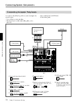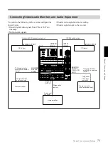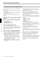
Chapter 3 Connections and Settings
69
Chapter 3 Connections and Settings
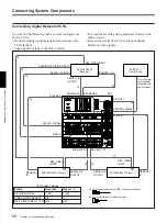
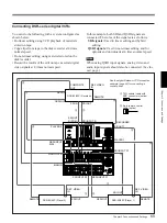
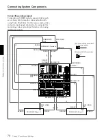
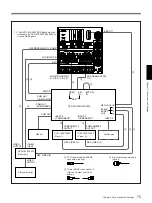
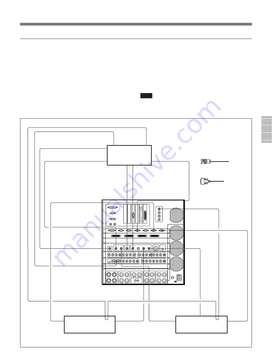
Connecting DSR-series digital VCRs
In this example, both SDI and QSDI signals are
connected. The roles of the signals are as follows.
SDI signals: Used in linear editing and hybrid
editing.
QSDI signals:
Used in non-linear editing and for
uploads and downloads at 4 times normal speed.
Note
When using QSDI input signals, analog video and
audio input signals should also be connected. (See the
next page.)
2
9-pin remote control
cable (option)
1
75
Ω
coaxial cable with
BNC connectors (option)
See the digital Betacam VCR connection
example (page 68) for connecting a
control panel.
DSR-85/85P (Recorder)
DSR-85/85P (Player 1)
DSR-85/85P (Player 2)
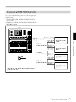
You can do the following with a system configured as
shown below.
• Do linear editing using VCR playback of materials
stored on tape.
• Copy clips from tape to the disk recorder at 4 times
normal speed.
• Do non-linear editing using materials stored on the
disk recorder.
• Record the results of the edit on tape as serial digital
video signals at 4 times normal speed.
COMPOSITE
OUT
QSDI IN
QSDI OUT
REF. VIDEO
IN
REMOTE
QSDI INPUT
R/P2
RECORDER
PLAYER 2
QSDI OUT R
MON IN
REMOTE
REF. VIDEO
IN
SDI OUT
QSDI INPUT P1
SDI INPUT P2
SDI OUT
SDI IN
SDI OUT
R (PGM)
SDI INPUT R
B B OUT 1
PLAYER 1
SDI INPUT P1
REF. VIDEO
IN
SDI OUT
QSDI OUT
REMOTE
1
1
1
2
1
1
2
2
1
1
1
1
1

