Chapter 3 Connections and Settings
67
Chapter 3 Connections and Settings
Connecting System Components
This section provides examples that show how to
connect the components in your editing system.
Connecting VCRs
The VCR connection examples in this section assume
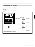
that an ESBK-7045 Disk Unit has been connected to
the EditStation.
For more information about connecting a disk unit, see page
71.
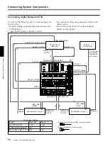
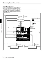
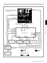
Connecting analog VCRs
You can do the following with a system configured as
shown below.
• Do linear editing using materials stored on tape and
VCR playback.
• Copy clips from tape to the disk recorder.
• Do non-linear editing using materials stored on the
disk recorder.
• Record the results of the edit on tape as analog
component video signals.
VCR switch settings
Switch
Recorder
Player 1, 2
REMOTE/LOCAL
REMOTE
REMOTE
VIDEO IN
Y–R, B
—
REF. VIDEO 75
Ω
ON
OFF
1
Cable with XLR connectors
(option)
2
75
Ω
coaxial cable with
BNC connectors (option)
UVW-1800/1800P,
PVW-2800/2800P
(Recorder)
See the digital Betacam VCR connection example (page 68) for
connecting a control panel.
AUDIO INPUT
CH-1, CH-2
COMPONENT 2 OUTPUT
REF. VIDEO INPUT
VIDEO 1 OUTPUT
REMOTE
RECORDER INPUT
B–Y, R–Y, Y/COMP
RECORDER
ES-7
PLAYER 2
PLAYER 2
INPUT B–Y,
R–Y, Y/COMP
MON IN
LINE
OUTPUT 1, 2
REMOTE
COMPONENT 2
OUTPUT
REF. VIDEO INPUT
AUDIO OUTPUT
CH-1, CH-2
RECORDER
INPUT 1, 2
AUDIO OUTPUT
CH-1, CH-2
COMPONENT 2
INPUT
PROGRAM OUTPUT
B–Y, R–Y, Y/G
B B OUT 1
PLAYER 1
PLAYER 1
INPUT B–Y,
R–Y, Y/COMP
PLAYER 1
INPUT 1, 2
PLAYER
INPUT 1, 2
REF. VIDEO INPUT
AUDIO OUTPUT
CH-1, CH-2
REMOTE
COMPONENT 2
OUTPUT
1
2
1
2
3
2
1
2
3
2
1
2
3
2
2
3
9-pin remote control cable
(option)
UVW-1800/1800P,
PVW-2800/2800P
(Player 2)
UVW-1800/1800P,
PVW-2800/2800P
(Player 1)

