5-9
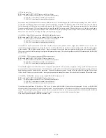
(7-5) 64020/64021 DRAM
ROM data
→
AVD
→
DRAM
→
AVD read-out then agreement check
Error
03: Data write error
04: Data read error
05: Write data and read data do not agree.
06: DMA transfer DREQ error
07: DMA transfer address error
In this test, the ROM pattern is copied to the entire area to be checked. During this copying, address of the copy source (ROM) is
returned by 254 bytes after every copying of 256 bytes. When the detailed check mode is selected, the same check is repeated in order
to test all bits using the inverted data. DMA is used for writing and reading.
The bus width of AVS decoder is 64 bits, however it is displayed in units of 8 bits. In other words, please note that the actual address is
1/8 of the display value, and the lower 3 bits shows position of byte. By means of reading after writing data in the entire area, the
overwriting by shadow can be checked . In the detailed check mode, the entire area is checked twice using the inverted data. In the
simple check mode, when one block is checked, the succeeding four blocks are not checked.
If write data and read data do not agree., check can be repeated.
(7-6) Connection from ARP to 64020/64021
ROM Data
→
ARP
→
Decrypt
→
AVD
Error
04: Data read error
05: Write data and read data do not agree.
06: DMA transfer DREQ error
07: DMA transfer address error
10: Data transfer error between chips
This check is performed as follows. The AC-3 audio data that is stored in ROM, is written first. Check if the data is transferred to the
AV decoder. If the transfer error is not detected, the target address of AV decoder to which the transfer data is written. A part of the data
that is transferred to the AV decoder is sent to the SH RAM using DMA and is compared with the ROM data.
(7-7) 64020/64021 interrupt line
AVD DRAM
→
(DMA copy) AVD DRAM separate area
Error
31: AVS decoder interrupt is not detected.
The interrupt showing the end of transfer, which is generated by copying the AVS decoder DRAM data to the other area using DMA
copy, is detected for this test.
(7-8) AV decoder revision check
Read from register
Error: Error is not detected.
The revision number of the AV decoder is read and displayed. The following displays appear depending upon the modes.
RS232C Line
RS232C Rough, Fine & Remote microprocessor
L64020 Rev.?
1 020?
AVD Rev. = L64020?
L64020 Rev.G
1 0204
AVD Rev. = L64020G
L64021 Rev.A
1 0210
AVD Rev. = L64021A
L64021 Rev.?
1 021?
AVD Rev. = L64021?
*
The register is a 8-bit register. When the line check is performed, 0200h is added to the read-out value. In other checks, it is replaced by
‘0G’ when the read-out value is ‘04’, and is replaced by ‘1A’ when the read-out value is ‘10’, and the character string is output following
‘L6402’. When the register value of the new version is fixed, the character string could be replaced.
Содержание DVP-M35
Страница 9: ...1 1 DVP M35 SECTION 1 GENERAL This section is extracted from instruction manual ...
Страница 10: ...1 2 ...
Страница 11: ...1 3 ...
Страница 12: ...1 4 ...
Страница 13: ...1 5 ...
Страница 14: ...1 6 ...
Страница 15: ...1 7 ...
Страница 16: ...1 8 ...
Страница 17: ...1 9 ...
Страница 18: ...1 10 ...
Страница 19: ...1 11E ...
Страница 32: ......
Страница 33: ...DVP M35 TK 47 RF SERVO SCHEMATIC DIAGRAM Ref No TK 47 Board 3 000 Series 4 7 4 8 4 9 RF SERVO TK 47 DVP M35 ...
Страница 34: ......
Страница 43: ......
Страница 45: ......
Страница 46: ......
Страница 48: ......
Страница 50: ......


