5-16
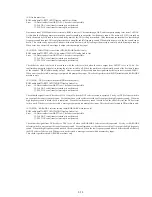
(10-10) AC-3 to 2 ch (DCS path)
AC-3 DSP test tone
→
2 ch DAC
→
Audio Out
Error
35: 2 ch DAC serial transfer interrupt is not detected.
37: PLL DAC serial transfer interrupt is not detected.
Test tone from the AC-3 decoder is output from the 2 ch L and R terminals. When error is not detected, a message is output which
prompts key input.
(11) KARAOKE related items [The supported models only]
(11-2) KARAOKE DSP register
Write into serial register
→
Read from register and check if data agree
Error
04: Data read error
05: Write data and read data do not agree.
54: KARAOKE DSP (CXD2721Q) interrupt is not detected.
62: KARAOKE DSP does not become ready.
The 16 different patterns of data that are generated by shifting data to the left by one bit starting from 0x0001, are written into RAM
address 0x00 of KARAOKE DSP. This check is performed by writing data then reading again. If write data and read data do not agree,
check can be repeated.
(11-3) KARAOKE DSP Reset line
Write into register
→
Resetting hardware
→
Read from register
Error
04: Data read error
05: Write data and read data do not agree.
54: KARAOKE DSP (CXD2721Q) interrupt is not detected.
62: KARAOKE DSP does not become ready.
This test is performed by writing 0x000fef to the KARAOKE DSP setup register address 0x00 and checks if the address is initialized to
0x000010 by reset pulse.
(11-4) KARAOKE DSP (serial)
ROM audio data
→
ARP
→
AVD
→
KARAOKE DSP
→
AOUT (Key control)
Error
10: Data transfer from ARP
→
to AV decoder is not possible.
35: 2 ch DAC serial transfer interrupt is not detected.
37: PLL DAC serial transfer interrupt is not detected.
54: KARAOKE DSP(CXD2721Q) interrupt is not detected.
62: KARAOKE DSP does not become ready.
This test checks if tone key is change in accordance with the setting of KARAOKE DSP. Natural sound is output, firstly, and tone key
is lowered by 8 steps and is output. When error is not detected, a message is output which prompts key input.
(11-5) Sound effect IC
Sound effect generation
→
analog out
Error
60: Sound effect IC does not become ready.
61: Sound effect IC does not become busy.
Clapping and cheers are output from the sound effect ICs. Clapping only for first time. Clapping with cheers in the second time. When
error is not detected, a message is output which prompts key input. Output is supplied to both of 2ch and 6ch at the same time. When
any key is not input, cheers keep output. Check the respective outputs.
Содержание DVP-M35
Страница 9: ...1 1 DVP M35 SECTION 1 GENERAL This section is extracted from instruction manual ...
Страница 10: ...1 2 ...
Страница 11: ...1 3 ...
Страница 12: ...1 4 ...
Страница 13: ...1 5 ...
Страница 14: ...1 6 ...
Страница 15: ...1 7 ...
Страница 16: ...1 8 ...
Страница 17: ...1 9 ...
Страница 18: ...1 10 ...
Страница 19: ...1 11E ...
Страница 32: ......
Страница 33: ...DVP M35 TK 47 RF SERVO SCHEMATIC DIAGRAM Ref No TK 47 Board 3 000 Series 4 7 4 8 4 9 RF SERVO TK 47 DVP M35 ...
Страница 34: ......
Страница 43: ......
Страница 45: ......
Страница 46: ......
Страница 48: ......
Страница 50: ......


