5-15
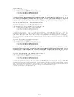
(10-6) AC-3 DSP test tone
AC-3 DSP 5 channel sequential test tone output
Error
43: AC3 DAC (For main output) serial transfer interrupt is not detected.
44: AC3 DAC (For center output) serial transfer interrupt is not detected.
45: AC3 DAC (For surround output) serial transfer interrupt is not detected.
55: AC3 decoder serial transfer interrupt is not detected.
Test tone from the AC-3 decoder is output to the left, right, left surround, right surround and center in this order. Then the surround left
and right are output at the same time using MGA. When error is not detected, a message is output which prompts key input.
(10-7) AC-3 audio output
ROM audio data
→
ARP
→
AVD
→
DIR
→
AC3 DSP
→
AC3 DAC
→
Audio signal output
Error
10: Data transfer from ARP
→
to AV decoder is not possible.
35: 2 ch DAC serial transfer interrupt is not detected.
37: PLL DAC serial transfer interrupt is not detected.
43: AC3 DAC (For main output) serial transfer interrupt is not detected.
44: AC3 DAC (For center output) serial transfer interrupt is not detected.
45: AC3 DAC (For surround output) serial transfer interrupt is not detected.
52: DIR serial transfer interrupt is not detected.
55: AC3 decoder serial transfer interrupt is not detected.
56: DIR does not lock in.
The AC-3 bit stream data that is stored in ROM is sent to AV decoder through ARP. The decoded audio data is output from AC-3 DAC
in the form of analog through DIR and AC-3 DSPs. When error is not detected, a message is output which prompts key input.
(10-8) Analog gain switch check
AC-3 DSP test tone
→
AC3 DAC
→
Audio Out (Analog Gain On/Off)
Error
43: AC3 DAC (For main output) serial transfer interrupt is not detected.
44: AC3 DAC (For center output) serial transfer interrupt is not detected.
45: AC3 DAC (For surround output) serial transfer interrupt is not detected.
55: AC3 decoder serial transfer interrupt is not detected.
The test tone is output from the front channel by setting the analog gain switch to on. For confirmation, the analog gain switch is turned
off again to output the tone. Be careful that the sound of the first time is larger because gain is increased. When error is not detected, a
message is output which prompts key input.
(10-9) AC-3 DAC (serial)
AC-3 DSP test tone
→
AC3 DAC
→
Audio Out (Attenuation)
Error
43: AC3 DAC (For main output) serial transfer interrupt is not detected.
44: AC3 DAC (For center output) serial transfer interrupt is not detected.
45: AC3 DAC (For surround output) serial transfer interrupt is not detected.
55: AC3 decoder serial transfer interrupt is not detected.
The AC-3 decoder test tone is output in the order of left, right, left surround, right surround and center. However, output of both
channels are attenutated gradually by DAC. When error is not detected, a message is output which prompts key input.
Содержание DVP-M35
Страница 9: ...1 1 DVP M35 SECTION 1 GENERAL This section is extracted from instruction manual ...
Страница 10: ...1 2 ...
Страница 11: ...1 3 ...
Страница 12: ...1 4 ...
Страница 13: ...1 5 ...
Страница 14: ...1 6 ...
Страница 15: ...1 7 ...
Страница 16: ...1 8 ...
Страница 17: ...1 9 ...
Страница 18: ...1 10 ...
Страница 19: ...1 11E ...
Страница 32: ......
Страница 33: ...DVP M35 TK 47 RF SERVO SCHEMATIC DIAGRAM Ref No TK 47 Board 3 000 Series 4 7 4 8 4 9 RF SERVO TK 47 DVP M35 ...
Страница 34: ......
Страница 43: ......
Страница 45: ......
Страница 46: ......
Страница 48: ......
Страница 50: ......


