6
SECTION 2
GENERAL
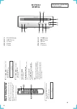
1
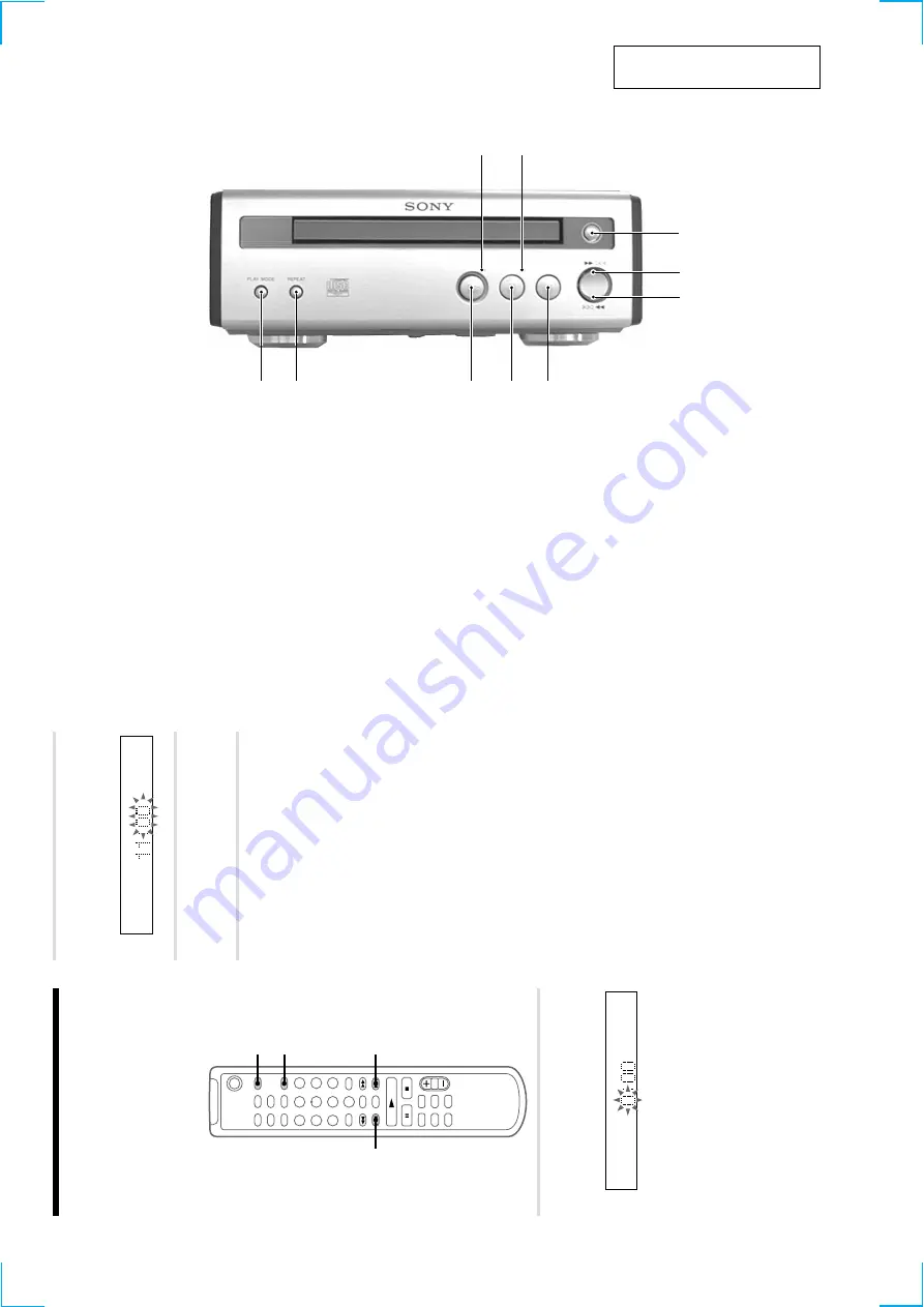
PLAY MODE button
2
REPEAT button
3
H
button
4
S
button
5
s
button
q;
9
1
2
3
4
5
7
6
8
6
lm
button
7
ML
button
8
A
button
9
S
indicator
q;
H
indicator
8
Step 2: Setting the time
Y
ou must set the time beforehand to use the timer
functions.
The clock is on a 24-hour system for the European
model, and a 12-hour system for other models.
The 24-hour system is used for illustration
purposes.
Set the time before turning on the system.
`/1
1
2,3
2,3
2,3
1
Press CLOCK/TIMER SET while the
system is of
f.
The hour indication flashes.
2
Press
.
or
>
to set the hour
,
then
press ENTER/YES.
The minute indication flashes.
3
Press
.
or
>
to set the minute,
then press ENTER/YES.
The clock starts.
If y
ou made a mistake
Start o
v
er from step 1.
T
o
c
hang
e the preset time
Y
ou can change the preset time while the system
is on.
1
Press CLOCK/TIMER SET
.
2
Press
.
or
>
repeatedly until “SET
CLOCK” appears, then press ENTER/YES.
3
Repeat steps 2 and 3.
Tips
•
The b
uilt-in clock sho
ws the time in the display
while the system is of
f. If you press DISPLA
Y at
this time, the display back light lights up, making
the clock easier to see.
•
The upper dot of the colon flashes for the f
irst 30
seconds, and the lo
wer dot flashes for the last 30
seconds of each minute.
This section is extracted from
instruction manual.
Содержание CMT-SP55TC
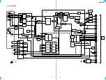
Страница 18: ...CDP SP55 17 17 5 4 SCHEMATIC DIAGRAM BD SECTION See page 14 for Waveforms See page 20 for IC Block Diagrams ...
Страница 20: ...CDP SP55 19 19 5 6 SCHEMATIC DIAGRAM MAIN SECTION See page 21 for IC Block Diagrams ...
Страница 60: ...ST SP55 6 6 3 3 SCHEMATIC DIAGRAM MAIN SECTION Page 8 Page 8 Page 8 PIN FUNCTION ...
Страница 62: ...ST SP55 8 8 3 5 SCHEMATIC DIAGRAM PANEL SECTION Page 6 Page 6 Page 6 LCD BACK LIGHT ...
Страница 102: ...8 MEMO ...
Страница 105: ...TA SP55 11 11 4 3 SCHEMATIC DIAGRAM MAIN SECTION ...
Страница 107: ...TA SP55 13 13 4 5 SCHEMATIC DIAGRAM PANEL SECTION ...
Страница 131: ...CDP SP55 17 17 5 4 SCHEMATIC DIAGRAM BD SECTION See page 14 for Waveforms See page 20 for IC Block Diagrams ...
Страница 133: ...CDP SP55 19 19 5 6 SCHEMATIC DIAGRAM MAIN SECTION See page 21 for IC Block Diagrams ...
Страница 146: ...ST SP55 6 6 3 3 SCHEMATIC DIAGRAM MAIN SECTION Page 8 Page 8 Page 8 PIN FUNCTION ...
Страница 148: ...ST SP55 8 8 3 5 SCHEMATIC DIAGRAM PANEL SECTION Page 6 Page 6 Page 6 LCD BACK LIGHT ...

