- 2 -
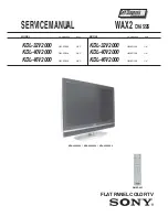
WAX2
RM-ED005
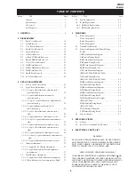
TABLE OF CONTENTS
Section
Title
Page
Section
Title
Page
Caution ................................................................
3
Specifications ......................................................
4
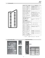
Connectors ..........................................................
6
Self Diagnosis .....................................................
7
1. GENERAL
...................................................................
8
2. DISASSEMBLY
2-1.
Rear Cover Removal ...........................................
18
2-2.
Stand Removal ....................................................
18
2-3.
Vesa Bracket Removal ........................................
19
2-4.
Shield Cover Removal ........................................
19
2-5.
Speaker Removal ................................................
20
2-6.
AC Inlet Removal ...............................................
20
2-7.
AE and TUE Board Removal .............................
21
2-8.
BE and FEE Board Removal ..............................
21
2-9.
G1 or G2 Board Removal ...................................
22
2-10. H1E Board Removal ...........................................
22
2-11. H2E or H46E Board Removal ............................
23
2-12. H4E Board Removal ...........................................
23
2-13. Shield Base Removal ..........................................
24
2-14. LCD Panel Removal ...........................................
24
3. SET-UP ADJUSTMENTS
3-1.
How to enter Service Mode ...............................
25
3-2.
Signal Level Adjustment ....................................
25
3-2-1. Set up of AD calibration1 adjustment for
terrestrial analog ...............................................
25
3-2-2. Y signal calibration1 adjustment for
terrestrial analog ...............................................
25
3-2-3. Set up of C signal calibration1 adjustment for
terrestrial analog ...............................................
25
3-2-4. C signal calibration1 adjustment for
terrestrial analog ...............................................
26
3-2-5. Set up of AD calibration1 adjustment for
video ................................................................
26
3-2-6. Y signal calibration1 adjustment for video ......
26
3-2-7. Set up of C signal calibration1 adjustment for
video ................................................................
26
3-2-8. C signal calibration1 adjustment for video ......
26
3-2-9. Set up of AD calibration2 adjustment for
video ................................................................
26
3-2-10. Y signal calibration2 adjustment for video ....
26
3-2-11. Set up of C signal calibration2 adjustment for
video ..............................................................
27
3-2-12. C signal calibration2 adjustment for video ....
27
3-3.
Gamma Adjustment ...........................................
27
3-3-1. Set up mode for Gamma Adjustment ..............
27
3-3-2. Set up Trident internal SG and brightness
measurement ....................................................
27
3-4.
White Balance Adjustment .................................
27
3-4-1. Set up mode for White Balance Adjustment ...
27
3-4-2. White Balance of colour temperature “High” ..
27
3-5.
Panel Replacement .............................................
29
3-6.
Board Replacement ............................................
29
3-6-1. AE Board Replacement ...................................
29
3-6-2. BE Board Replacement ....................................
29
4. DIAGRAMS
4-1.
Block Diagrams(1) .............................................
30
Block Diagrams(2) .............................................
31
Block Diagrams(3) .............................................
32
Block Diagrams(4) .............................................
33
4-2.
Circuit Board Location ........................................
33
4-3.
Schematic Diagrams and Printed Wiring
Boards .................................................................
33
AE Board Schematic Diagram ............................
34
AE Printed Wiring Board .................................
38
BE Board Schematic Diagram ............................
40
BE Printed Wiring Board ...................................
50
FEE Board Schematic Diagram ..........................
52
FEE Printed Wiring Board .................................
58
G2 Board Schematic Diagram
(KDL-40V2000, KDL-46V2000) ......................
59
G2 Printed Wiring Board
(KDL-40V2000, KDL-46V2000) ...................
60
H1E Board Schematic Diagram ..........................
62
H1E Printed Wiring Board ...............................
63
H2E Board Schematic Diagram ..........................
62
H2E Printed Wiring Board ...............................
63
H4E Board Schematic Diagram ..........................
62
H4E Printed Wiring Board ...............................
63
H46E Board Schematic Diagram
(KDL-46V2000) .................................................
64
H46E Printed Wiring Board
(KDL-46V2000) .................................................
63
TUE Schematic Diagram ....................................
64
TUE Printed Wiring Board ...............................
66
4-4.
Semiconductors ..................................................
67
5. EXPLODED VIEWS
5-1.
Chassis ................................................................
69
5-2.
Rear Cover, Stand and Vesa Bracket ..................
70
6. ELECTRICAL PARTS LIST
.................................. 71
SAFETY-RELATED COMPONENT WARNING !!
COMPONENTS IDENTIFIED BY SHADING AND MARKED
ON
THE SCHEMATIC DIAGRAMS, EXPLODED VIEWS AND IN THE
PARTS LIST ARE CRITICAL FOR SAFE OPERATION. REPLACE
THESE COMPONENTS WITH SONY PARTS WHOSE PART
NUMBERS APPEAR AS SHOWN IN THIS MANUAL OR IN
SUPPLEMENTS PUBLISHED BY SONY.
WARNING !!
AN ISOLATION TRANSFORMER SHOULD BE USED DURING
ANY SERVICE WORK TO AVOID POSSIBLE SHOCK HAZARD
DUE TO LIVE CHASSIS, THE CHASSIS OF THIS RECEIVER IS
DIRECTLY CONNECTED TO THE POWER LINE.
Содержание BRAVIA KDL-32V2000
Страница 19: ... 18 WAX2 RM ED005 SECTION 2 DISASSEMBLY 2 2 STAND REMOVAL 2 1 REAR COVER REMOVAL ...
Страница 20: ... 19 WAX2 RM ED005 2 3 VESA BRACKET REMOVAL 2 4 SHIELD COVER REMOVAL ...
Страница 21: ... 20 WAX2 RM ED005 2 5 SPEAKER REMOVAL 2 6 AC INLET REMOVAL ...
Страница 22: ... 21 WAX2 RM ED005 2 7 AE and TUE BOARD REMOVAL 2 8 BE and FEE BOARD REMOVAL ...
Страница 23: ... 22 WAX2 RM ED005 2 9 G1 or G2 BOARD REMOVAL 2 10 H1E BOARD REMOVAL ...
Страница 25: ... 24 WAX2 RM ED005 2 13 SHIELD BASE REMOVAL 2 14 LCD PANEL REMOVAL ...
Страница 40: ...A B C D E F G H I J K L M N 1 2 3 4 5 6 7 8 9 10 11 O 39 AE Printed Wiring Board Conductor Side B ...
Страница 100: ...9 927 532 01 Sony Corporation Sony UK Service Promotions Dept English 06DP7100 1 Printed in U K 2006 04 ...

