SolarMax SM30HT4 Скачать руководство пользователя страница 1

Instruction manual

SolarMax HT series

30HT4 / 32HT4

Содержание SM30HT4

Страница 1: ...Instruction manual SolarMax HT series 30HT4 32HT4...

Страница 2: ...inverters 14 4 2 Lifting the inverter 14 4 3 Checking the delivery for completeness 15 4 4 Selecting the installation location 16 4 5 Mounting the inverter 18 5 Electrical connection 21 5 1 Removing t...

Страница 3: ...7 4 Displaying Main Menu 53 7 5 Statistics 54 7 5 1 Displaying the daily statistics 54 7 5 2 Displaying the monthly statistics 54 7 5 3 Displaying the annual statistics 55 7 5 4 Displaying the total s...

Страница 4: ...10 2 Dismounting the inverter 64 10 3 Disposing of the inverter 65 11 Technical data 66 11 1 Efficiency curve 68 11 2 Temperature dependent output reduction 68 11 3 MaxComm compatibility 69 11 4 Coun...

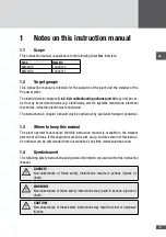
Страница 5: ...4 should only be carried out by specialist transport personnel 1 3 Where to keep this manual The plant operator must ensure that this instruction manual is available to the relevant persons at all ti...

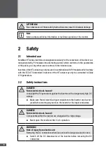
Страница 6: ...the IEC 61730 standard Inverters of the HT series may only be connected to Class II PV generators 2 2 Safety instructions DANGER Fatal electric shock hazard In daylight the PV generator supplies the i...

Страница 7: ...Proceed to wait for 5 minutes before opening the inverter Only qualified electricians may perform work on the inverter Operating instructions Please read and follow the instructions supplied with the...

Страница 8: ...V generator on or off at any time The components of the inverter remain live even when the DC disconnector is switched off Remote monitoring For the purpose of monitoring the PV plant remotely Etherne...

Страница 9: ...g on the generator side This sensor can distinguish between the oper ational capacitive stray currents caused by capacities of the PV modules to ground and leakage currents caused by touching a pole o...

Страница 10: ...10 3 4 Dimensions mm 590 580 397 847 871 Figure 1 Dimensions with wall mounting bracket...

Страница 11: ...en 11 3 5 Views of the unit 2 3 4 12 11 9 10 8 7 7 6 1 5 Figure 2 Views of the unit...

Страница 12: ...plate 5 Safety brackets 6 Wall mounting bracket 7 Handles for lifting the inverter by hand 8 Ventilation outlet 9 AC mains cable gland AC input conductor 10 COMM multiple cable gland for communication...

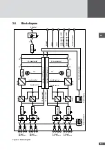
Страница 13: ...DC DC DC Control unit MPP tracker 1 2 Control unit MPP tracker 3 4 Graphics display DC disconnector Q1 DC input MPP tracker 1 DC input MPP tracker 2 DC input MPP tracker 3 DC input MPP tracker 4 AC o...

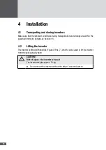
Страница 14: ...thin the specified limits for details see Section 11 4 2 Lifting the inverter The inverter is fitted with handles Figure 2 Pos 7 which can be used to lift the inverter from the packaging by hand CAUTI...

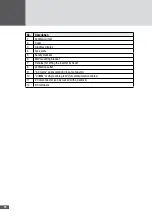
Страница 15: ...okumentation SolarMax HT Serie 30HT4 32HT4 2 3 4 5 6 7 8 9 10 11 12 13 1 14 15 16 17 Figure 4 Content of delivery No Quantity Description 1 1 Inverter 2 1 Instruction manual 3 16 Locking clip for lock...

Страница 16: ...ter is an electrical device with heat generation and the possibility of sparking Install the inverter in an environment that is free of flammable gases and fluids Never install the inverter near combu...

Страница 17: ...Unacceptable mounting positions Appropriate cooling of the inverter can only take place when the ventilation openings on the sides are kept clear The ambient air around the inverter must be free from...

Страница 18: ...re included in the delivery Fixing the mounting plate 1 Use the mounting plate as a drilling template 2 Use a spirit level to align the mounting plate horizontally 3 Mark 6 places for drilling 205 553...

Страница 19: ...e M6 washers 6 x 60 Torx pan head screws Figure 8 Fixing the mounting plate Engage the inverter in the mounting plate 6 With the help of a second person engage the inverter in the seats of the mountin...

Страница 20: ...8 Secure the inverter with the 2 safety brackets included in the delivery Installation sequence 10 x 50 wall plugs safety bracket M6 washers 6 x 60 Torx pan head screws Figure 10 Securing the inverter...

Страница 21: ...all control cables connected to the inverter status relays external grid monitoring and shut down 3 Switch off the DC disconnector at the inverter DANGER Fatal electric shock hazard Components within...

Страница 22: ...network connections status signaling contacts external shutdown 3 AC mains cable gland for the AC input conductor 4 M5 threaded PE bolt for the connection of the second protective conductor optional...

Страница 23: ...gested mains fuses Minimum conductor cross sections 30HT4 32HT4 Phases L1 L2 L3 10 mm2 10 mm2 Neutral conductor N 4 mm2 4 mm2 Protective conductor PE 10 mm2 10 mm2 Recommended mains fuses 30HT4 32HT4...

Страница 24: ...and L3 Tightening torque 4 to 4 5 Nm L2 L3 PE 4 4 5 Nm M5 N L1 19 mm Figure 13 AC connection 5 Check the cable connections for firm seating 6 Tighten the M40 cable gland 7 Check the cable strain relie...

Страница 25: ...nverter to the PV generator The HT series inverters have four independent MPP trackers which can be used to con nect strands with different characteristics such as orientation size and module type Eac...

Страница 26: ...used in order to connect more strands than specified each DC input conductor must be protected individually against dan gerous return currents Parallel connection of the MPP trackers is not permitted...

Страница 27: ...parts made by Wieland www wieland electric com for plug component order number 05 566 6380 0 for socket component order number 05 566 6480 0 5 5 Network connections optional The inverter has one Ether...

Страница 28: ...mation MaxComm network You can download this document from our web site at www solarmax com Downloads Data Communication MaxComm Connection conditions Connection types 3 x RJ45 sockets 4 pole plug in...

Страница 29: ...ips Figure 19 No 3 6 Close off the unused apertures in the multiple cable glands using the locking pins No 8 in Section 4 3 7 Tighten the multiple cable gland wrench size 34 mm 8 Fit the cover of the...

Страница 30: ...onnection type 6 pole connector included in the delivery Connectable conductor cross sections min 0 25 mm2 max 2 5 mm2 Multiple cable gland usable cable 5 5 to 7 0 mm Max switching voltage 250 VAC 30...

Страница 31: ...3 7 Close off any unused apertures in the multiple cable gland using the locking pins see No 8 in Section 4 3 8 Tighten the multiple cable gland wrench size 34 mm 9 Fit the cover of the inverter 5 7...

Страница 32: ...y one contact is connected only that one MPP tracker will feed into the grid When the status signaling contacts are in use see Section 5 6 the external shutdown function cannot be used Connection cond...

Страница 33: ...ns No 8 in Section 4 3 9 Tighten the multiple cable gland wrench size 34 mm 10 Fit the cover of the inverter 5 8 External output control optional The MaxWebxp data logger and its MaxRemote extension c...

Страница 34: ...displayed This indicates that the inverter is in mains operation During initial start up of the inverter instead of the Overview menu an Initial setup menu appears see Section 6 2 6 2 Initial start up...

Страница 35: ...dure 1 Switch on the inverter as described in Section 6 1 The Initial setup menu will be displayed Figure 25 Selecting the display language and updating the system time 2 Select the display language f...

Страница 36: ...stem rating is higher than 30 kVA External grid monitoring will be used CosPhi Pac QMCPP Inactive The cos Pac function is deactivated cos 1 On The cos Pac function is activated only available with the...

Страница 37: ...n is working the inverter triggers the grid monitoring action For each step of the test the graphics display shows the current reading the trigger value the trip time and the set limit During the test...

Страница 38: ...d monitoring functions can be set in the Set tings menu of the graphics display All settings except the IP mode can also be made using the MaxTalk service software 6 4 1 Changing parameters The parame...

Страница 39: ...ime The inverter s display language and system time can be changed in the Settings menu 1 Select the Settings menu Figure 30 Changing the display language and system time 2 Select the parameter and up...

Страница 40: ...settings must be made to communicate via Ethernet 1 In the Main Menu select the Network menu 2 In the IP mode select the required setting Setting Description DHCP client The inverter is a DHCP client...

Страница 41: ...ter the expiry of the adjustable delay time The status signaling contact opens when the error has been eliminated factory setting On When a power unit MPP tracker 1 2 or MPP tracker 3 4 switches on wh...

Страница 42: ...s external shutdown and external output control Inverter start up Those functions are displayed which are active before the inverter is connected to the grid start conditions Grid operation Those func...

Страница 43: ...itoring RCMUT ENA RCMUT function status Disabled enabled IST Checking the grid relay IST ENA IST function status Disabled enabled GPT Checking the grid parameters GPT ENA GPT function status Disabled...

Страница 44: ...Checking the maximum permissible mains voltage limit 2 GVMMAX2 ENA GVMMAX2 function status Disabled enabled GVMMAX2 THR Limit value V GVMMAX2 DLY Trip time s GVM10AMAX Checking the maximum permissible...

Страница 45: ...the leakage current step value RSCM ENA RSCM function status Disabled enabled DCCIM Monitoring the DC component in the AC current DCCIM ENA DCCIM function status Disabled enabled DCCIM THR Maximum per...

Страница 46: ...PFLM3 UFQTHR Maximum permissible mains frequency Hz PFLM3 LFQTHR Minimum permissible mains frequency Hz PFLM3 UVTHR Maximum permissible mains voltage V PFLM3 LVTHR Minimum permissible mains voltage V...

Страница 47: ...e Q Vac mode 1 QMQU1 VSP1 to VSP10 Characteristic values 1 to 10 of mains voltage Vac V QMQU1 CPSP1 to CPSP10 Characteristic values 1 to 10 of reactive power Q of Pac nom UEX OEX QMQU1_DLY Delay time...

Страница 48: ...switch off value W Grid stabilization Functions and parameters of the Grid stabilization sub menu Function parameter Description Unit FRT Fault Ride Through function FRT ENA FRT function status Disab...

Страница 49: ...ues Measured values under System Measured value Description Unit Vac L1 Vac L2 Vac L3 Phase voltage L1 L2 and L3 V Iac L1 Iac L2 Iac L3 Output current L1 L2 and L3 A Pac Output power W S Apparent powe...

Страница 50: ...ed to display in addition the following mea sured values of the inverter Measured value Description Unit Vac 10 min 10 minute mean value of the mains voltage V Iac mean Mean value of output current A...

Страница 51: ...4 5 Figure 33 Graphics display with the standard Overview display No Description 1 Graphics display with backlighting 2 Status LED operating status display see Section 7 7 3 Function keys membrane ke...

Страница 52: ...aly Time Language Date Device adress Days Months Years Total Reset Network IP IP Mode Netmask Gateway TCP Port DNS1 DNS2 Status relay Status relay delay SSF Settings Grid operation External input Inve...

Страница 53: ...Figure 35 Overview menu Display Description 19 06 2013 11 44 35 Date and system time of inverter examples Pac Output power W Today Daily yield kWh Total Total yield since commissioning kWh Status Oper...

Страница 54: ...or the last 31 days 1 In the Statistics menu select the Day sub menu Figure 37 Daily statistics 2 Press or to select the day Statistics value Description Yield Daily yield kWh Maximum Fed in maximum p...

Страница 55: ...ues for the last 25 years 1 In the Statistics menu select the Year sub menu Figure 39 Annual statistics 2 Press or to select the year Statistics value Description Yield Annual yield kWh Maximum Fed in...

Страница 56: ...cs values in the data logger can be deleted 1 In the Statistics menu select the Reset sub menu Figure 41 Resetting the inverter s data logger Note Once data are deleted this cannot be undone 2 Press t...

Страница 57: ...The status message which gives a more detailed description of the operating status is displayed at the graphics display In addition to the status messages the inverter also displays warnings Warnings...

Страница 58: ...operating status The status LED lights up green Status message Description Maximum output power The inverter limits the in feed power to the maximum possible value This may occur if the PV generator...

Страница 59: ...isplayed warnings and status messages are described in the Sec tions 7 7 and 8 2 1 In the Main Menu select the Status menu Figure 43 Status menu Entry Description System Operating status of inverter s...

Страница 60: ...l Bienne 8 2 Diagnosis and actions The following tables describe possible actions for remedying faults If the actions sug gested do not correct the fault please contact the SolarMax Service Center 8 2...

Страница 61: ...e Center Firmware mismatch The firmware versions of the inverter controllers do not match Contact the SolarMax Service Center Flash error An error has occurred in the flash memory Contact the SolarMax...

Страница 62: ...MMIN1 THR GVMMIN2 THR or GPTVMIN THR limit values Vac 10 min too high The maximum 10 minute average value of the mains voltage GVM10AMAX THR is too high DC insulation fault The insulation resistance o...

Страница 63: ...date is complete 9 Maintenance The following maintenance tasks should be carried out at regular intervals Check the operating status of the inverter see Section 7 7 Check that the ventilation inlet an...

Страница 64: ...s remain in the inverter for approx 5 minutes Before starting to dismount the inverter the inverter must be fully discon nected in accordance with the procedure described in this chapter WARNING Risk...

Страница 65: ...Fit the cover of the inverter 8 Remove the two safety brackets CAUTION Risk of injury the inverter is heavy The inverter weighs approx 70 kg Never dismount the inverter on your own 9 When dismounting...

Страница 66: ...ains voltage range 230 184 to 276 V Nominal mains frequency range 50 45 to 55 Hz Power factor cos Adjustable from 0 8 overexcited to 0 8 under excited Distortion factor at rated output power 3 Connect...

Страница 67: ...61643 11 Standards and guidelines CE compliant Yes2 EMC EN 61000 3 11 EN 61000 3 12 EN 61000 6 2 EN 61000 6 3 Grid connection VDE AR N 4105 VDE 0126 1 1 A1 2012 BDEW MS Directive G59 3 CEI 0 21 CEI 0...

Страница 68: ...Rated output power Efficiency Figure 45 Efficiency curve SolarMax HT series 11 2 Temperature dependent output reduction When the ambient temperature is too high the inverter reduces its output as ill...

Страница 69: ...s of the Ethernet interface can be set at the inverter s graphics display see Section 6 4 3 Individual device Gateway device Ethernet RS485 Ethernet MaxWebxp MaxTalk 2 MaxTalk 2 firmware update MaxVie...

Страница 70: ...the PV power plant MaxTalk Pro Professional version of MaxTalk for the configuration of inverters The SolarMax HT series parameter configuration using MaxTalk 2 Pro operating manual can be downloaded...

Страница 71: ...r replaced by SPUTNIK service personnel within a reasonable time in either case free of charge unless this is impossible or disproportionate SPUTNIK may decide at its own discretion whether a device w...

Страница 72: ...entioned in the paragraph above 4 Warranty Period in Case of Repair Replacement In case of repair or replacement of devices under this warranty the repaired respectively replaced device will inherit t...

Страница 73: ...e device by SPUTNIK Central Inverters The extension of the basic warranty can be ordered within 3 months after pur chase but the latest within 12 months after dispatch by SPUTNIK b Extent Full warrant...

Страница 74: ...SolarMax Service Center hotline solarmax com www solarmax com service 2014 05 en...

Отзывы: