background image

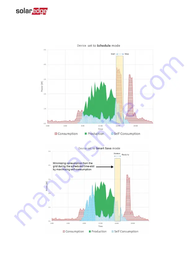
The following figure illustrates a typical example of device operation with Smart Save 

and Schedule modes. Note that in Smart Save mode, the consumption is reduced  by 

taking advantage of excess PV earlier in the day.

Figure 2: Examples of device operation


Smart Energy Hot Water Installation     

7

Smart Energy Hot Water Installation Guide MAN-01-00570-1.4

Содержание Smart Energy Hot Water

Страница 1: ...Installation Guide Smart Energy Hot Water Version 1 4...

Страница 2: ...y However discrepancies cannot be excluded No guarantee is made for the completeness of these documents The images contained in this document are for illustrative purposes only and may vary depending...

Страница 3: ...nnected Consult the dealer or an experienced radio TV technician for help Changes or modifications not expressly approved by the party responsible for compliance may void the user s authority to opera...

Страница 4: ...ith Inverters with SetApp 23 Modifying the Device Operation Mode and Schedules 24 Verifying the Connection 24 Troubleshooting Errors 26 Support Contact Information 29 Revision History Version 1 4 Nove...

Страница 5: ...Do not proceed beyond a warning note until the indicated conditions are fully understood and met CAUTION Denotes a hazard It calls attention to a procedure that if not correctly performed or adhered t...

Страница 6: ...er by 18 00 set the Duration to 2 hours and Ready by to 18 00 The boiler may work before 16 00 if there is available PV power but in any case you are guaranteed to have hot water by 18 00 Refer to Fig...

Страница 7: ...Figure 1 SolarEdge system with Smart Energy products Smart Energy Hot Water Installation Guide MAN 01 00570 1 4 6 Overview...

Страница 8: ...h Smart Save and Schedule modes Note that in Smart Save mode the consumption is reduced by taking advantage of excess PV earlier in the day Figure 2 Examples of device operation Smart Energy Hot Water...

Страница 9: ...olaredge meter installation guide na pdf Energy Meter with Cellular Connection Refer to https www solaredge com sites default files se_energy_ meter_cellular_na pdf ZigBee Plug in for Smart Energy Ref...

Страница 10: ...nnectors and interfaces of the device Figure 3 Device interfaces Cable connection glands ON OFF P Switch manages the device operation ON 1 Turning this switch ON starts the operation of the device OFF...

Страница 11: ...supply to immersion heater Switch moved to P for 5 10 seconds Starts pairing association of the device with the inverter The inverter provisions controls and connects the device to the monitoring pla...

Страница 12: ...h the inverter Blue ZigBee Wi Fi Communication link to the inverter Off Not paired with the inverter Blinking The device is paired with the inverter however not connected to the monitoring platform or...

Страница 13: ...supply e g fridge freezer Do not use the product if it is damaged or malfunctioning Never connect loads that can cause injuries or fire if they are switched on unintentionally e g an iron Do not let t...

Страница 14: ...imum distance from the inverter as shown below Figure 5 Clearance 2 Position the bracket against the wall pole level the bracket and mark the drilling hole locations Ensure that the U shaped indentati...

Страница 15: ...the bracket Connection Guidelines Make sure that power is disconnected from the main distribution panel Connect the device through a circuit breaker in the AC distribution panel Connect the device thr...

Страница 16: ...ting the Device 1 Turn OFF the AC circuit breaker of the main distribution panel 2 Release the four screws attaching the device cover to the enclosure and remove the cover Figure 8 Opening the cover C...

Страница 17: ...wrap the grounding wire in the opposite direction to the other wires c Connect the AC wires according to labels L N on the left terminal block 4 Connect to the immersion heater see Figure 9 CAUTION Do...

Страница 18: ...Attach the mounting clip with the antenna vertically to the top of the heat sink fins d Insert the antenna cable from the top of the device and route the cable downwards along and between the heat si...

Страница 19: ...he pre installed ZigBee Plug in see Figure 9 6 Close the device cover and fasten the screws 7 Turn ON the AC circuit breaker of the main distribution panel 8 Turn On the device by turning the ON OFF P...

Страница 20: ...tallation Guide for details on setting up communication Configuration with Inverters with an LCD Required inverter Firmware CPU version v3 25xx and later To associate the device with the inverter usin...

Страница 21: ...W x x x M a n O F F S E S P L G x x x M a n O F F R e m o v e A l l Device types SE SW Smart Energy Relay SE S PLG Smart Energy Socket SE S SW Smart Energy Switch 7 Select the device The device confi...

Страница 22: ...A d d S c h e d u l e D e v i c e P r o p e r t i e s D e v i c e I n f o R e m o v e D e v i c e 2 Select Device Properties and set the following properties L o a d R a t i n g x x K W M i n O n T i...

Страница 23: ...e longer due to diversion of excess PV energy Schedule S e t S c h e d u l e S t a r t T i m e 0 0 0 0 E n d T i m e 0 0 0 0 W e e k D a y s 1 2 3 4 5 6 7 Start End Time the time of day by which the S...

Страница 24: ...P position and hold for more than 5 seconds Press the association button for 2 seconds SetApp indicates that the device has been associated 7 After all required devices have been associated tap Stop i...

Страница 25: ...t Save Schedule Disable or delete a schedule only for inverters with an LCD Select Disable or Remove Schedule from the Schedule screen Verifying the Connection Inverters with LCD 1 Check the status sc...

Страница 26: ...applicable Inverters with SetApp Configuration 1 Go to Device Manager Device Info 2 Check that the following device details are correct MAC Address the full MAC address of the device Last Communicatio...

Страница 27: ...tions If problem is not solved proceed with the next option Turn the device OFF and ON Recheck communication Turn the device OFF and then repeat the association process Reconfiguration is not required...

Страница 28: ...the discovery process for all the devices Contact SolarEdge support No hot water The device is associated with the inverter blue LED is on but not delivering power to the load Try to solve using thes...

Страница 29: ...management network Remove an unused device from the device list before attempting to add another device The device is not functioning 1 Turn the inverter ON OFF P switch to OFF Wait 5 minutes for the...

Страница 30: ...d on the product SetApp mobile application LCD screen or on the monitoring platform or by the LEDs if there is such an indication System configuration information including the type and number of modu...

Страница 31: ...Type of Action Type 1 C COMMUNICATION Supported Communication Protocol ZigBee Home Automation Device Configuration Via the inverter LCD the monitoring platform app or SetApp Ethernet connection is re...

Страница 32: ...0 to 50 14 to 122 C F Conduits Support of and inch conduits 8 gauge wire Pre drilled opening of 1 109 in Terminal Block Minimum Wire Cross Section 15 1 5 AWG mm2 Maximum distance between Device and Lo...

Страница 33: ...Action Type 1 C COMMUNICATION Supported Communication Protocol ZigBee Home Automation Device Configuration Via the inverter LCD the monitoring platform app or SetApp Ethernet connection is required No...

Страница 34: ...kg lb Operating Temperature Range 10 to 50 14 to 122 C F Cable Gland Diameters 2 glands 6 12 1 gland 4 8 mm Terminal Block Minimum Wire Cross Section 15 1 5 AWG mm2 Maximum distance between Device an...

Страница 35: ...ce Rating 25 A Type of Action Type 1 C Over Voltage Category 2 III COMMUNICATION Supported Communication Protocol ZigBee Home Automation Device Configuration Via the inverter LCD the monitoring platfo...

Страница 36: ...to 122 C F Conduits Pre drilled openings of 25 mm for 2 conduits Terminal Block Minimum Wire Cross Section 15 1 5 AWG mm2 Maximum distance between Device and Load Cable cross section for load size 3 0...

Страница 37: ......

Отзывы: