TESTING VEHICLE WIRES
CONTINUED
WHEN LOOKING FOR A POSITIVE (+) WIRE CONNECT ONE LEAD OF YOUR MULTI METER TO A CHASSIS
GROUND.
WHEN LOOKING FOR A NEGATIVE (-) WIRE CONNECT ONE LEAD OF YOUR MULTI METER TO A 12V (+)
CONSTANT SOURCE
TRUNK RELEASE (-)
- This wire can usually always be found at the trunk release switch.
To test for this wire use a multi meter set to DC Voltage with one lead to 12V(+) Constant and the other lead to
probe for a wire that reads between 10-16Volts (-) when the trunk release is engaged. Connect this wire to the
Red/White wire on CN4. The output time can be adjusted in Menu 1-09
TRUNK RELEASE (+)
- This wire is usually coming from the BCM and is controlled from the factory keyless entry
remote.
To test for this wire use a multi meter set to DC Voltage with one lead to chassis ground and the other lead to
probe for a wire that reads between 10-16Volts (+) when the trunk release is engaged. We recommend that
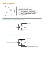
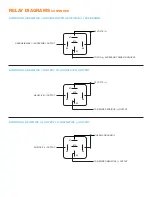
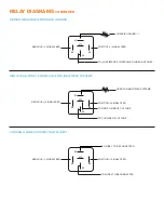
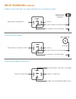
when connecting trunk in this way to isolate the switch with a relay. See Relay Guide. If the trunk release is (+)
directly from a trunk release switch then you can connect this wire to the Pink/White wire on CN1 and program
for Positive Trunk in Menu 2-01.
WAIT TO START/GLOW PLUG LIGHT (+/-)
- This wire can usually always be found at the instrument cluster or at
the ECM.
To test for this wire use a multi meter set to DC Voltage with one lead to 12V(+) Constant and the other lead to
probe for a wire that reads between 10-16Volts (-) with the ignition switch turned on and the Wait to Start bulb is
on. Once the Wait to Start Bulb goes out and the meter no longer reads 12V(-) this is a Negative (-) Wait to Start
Wire. If the Wait to Start wire reads 12V(-) when the light goes out then this wire is Positive (+). Connect this
wire to the Gray/Black wire on CN4. You can also set a desired Time delay in Menu 2-04
DOOR PIN (-)
- This wire can usually always be found at the door pin switch and can usually be found at the BCM
or at the instrument cluster.
To test for this wire use a multi meter set to DC Voltage with one lead to 12V(+) Constant and the other lead to
probe for the door pin wire. If the wire reads between 10-16Volts (-) when the door is open then the door pin is
negative (-) and you can connect the Green wire on CN4 to this wire.
DOOR PIN (+)
- This wire can usually always be found at the door pin switch and can usually be found at the
BCM or at the instrument cluster.
To test for this wire use a multi meter set to DC Voltage with one lead to Chassis Ground and the other lead to
probe for the door pin wire. If the wire reads between 10-16Volts (+) when the door is open then the door pin is
positive (+) and you can connect the Purple wire on CN4 to this wire.
DOOR PIN (OPEN)
- This wire can always be found at the door pin switch and can usually be found at the BCM
or at the instrument cluster.
To test for this wire use a multi meter set to DC Voltage with one lead to Chassis Ground and the other lead to
probe for the door pin wire. If the wire reads between 2-7 Volts when the door is open and nothing when it is
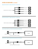
closed then the door pin is an open circuit and you need to follow the OPEN DOOR CIRCUIT DIAGRAM in the
DIODE GUIDE and connect the (+) wire to the Purple Wire on CN4.
*If connecting to circuit with a delay you can set the desired delay time in Menu 3-02.
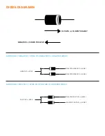
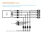
**Also be sure to check that all doors are monitored and there are multiple wires please isolate with diodes.
Please see DIODE GUIDE for install.
***For Rearm Situations when a door needs to be opened you can connect the Green/White wire on CN4 directly
to a Negative (-) door pin, or to a relay to switch to a positive for a Positive (+) door pin, or use the Green/White
wire on CN4 to cut the wire with a relay for Open Door circuit. Please refer to RELAY GUIDE for installation.
****All doors must be connected when installing into a MANUAL TRANSMISSION VEHICLE

