ITYS 6-10 kVA - 551431A - SOCOMEC
32
EN
5.5. Power cables connection
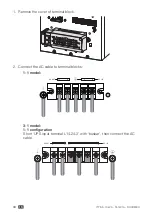
This chapter explains how to wire the AC IN/OUT cable to different UPS models
and how to connect the UPS with the EBM.
5.5.1. Input /Output wiring
Before wiring the UPS, the upstream breaker and backfeed contactor should be
configured to avoid power backfeed to the unit. The “backfeed voltage danger”
warning label should be added to the backfeed contactor or device. Before
operating, the UPS input should be cut off, and check the voltage on all the
terminals to avoid any dangerous voltages. Backfeed contactor rating current
should be higher than UPS rating input current. The figures below show the wiring
system of the UPS input and ouput.
Single phase input system
PE
PE
N
N
L
L
PE
N
L
PE
N
L
Breaker
Contactor
AC Input
AC Output
Switch
User’s
equipment
The breaker also can be
used as disconnect device
UPS
Coil
Three phase input system
PE
PE
N
N
L1
L1
L2
L2
L3
L3
N
L
N
L
PE
PE
Breaker
Contactor
AC Input
AC Output
Switch
User’s
equipment
The breaker also can be
used as disconnect device
UPS
Coil
Danger!
The rated current of the mains power supply switch must be
higher than the UPS input current, otherwise the mains power supply
switch may burn!
In three phase input system UPS the bypass connects directly input phase
R to the output: in this condition the load is connected to one phase like it
is on single phases input system UPS.


