


33
EN
ATyS / ATyS r - 541630C - SOCOMEC
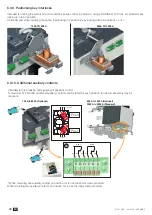
7.2. Control circuits
7.2.1. Typical ATy
S r wiring
Example:Controlwiringfora400VACapplicationhavinga3phaseandneutralsupply.
1
2
30
1302
2
312 313 314 315 316 317 63A64A 24 14 04 13
CONTROL
OUTPUTS
ATyS g Voltage Sensing
and Power supply Kit
(excludes the need for
fuses F1 & F2
Control Inputs from :
• Remote pushbuttons
• PLC Controller
• ATS controller
Fus. 4A
type gG
DANGER
Do not handle any control or power cables connected to the ATyS when voltage may be
present.
CAUTION
Verify that the Auxiliary power supply feeding terminals 301 and 302 are within the limits of
208VAC -> 277VAC ±20% (166-332VAC).
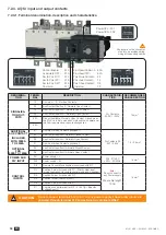
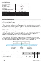
7.2.2. ATy
S r RTSE + ATS Controllers type AT
yS C25 and ATyS C55/C65
Refer to the relevant ATS controller instruction manual for ATyS C25 and ATyS C55/65 details
ATyS C25
Measurement and
power supply
Control and
position information
feedback
Generating set
«start/stop»
DCpowersupply
(optional)
U+F metering for each genset
Control and position information
feedback
Generatingset«start/stop»
control
External«start/stop»command
for basic cycle
DCpowersupply(optional)
ATyS C55/C65
Содержание ATyS r
Страница 3: ...3 EN ATyS ATyS r 541630C SOCOMEC ...
Страница 26: ...26 EN ATyS ATyS r 541630C SOCOMEC 6 3 4 Terminal screens 125A to 630A 500A to 1600A 2000A to 3200A ...
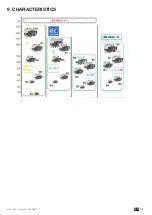
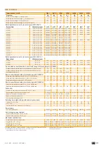
Страница 41: ...41 EN ATyS ATyS r 541630C SOCOMEC 9 CHARACTERISTICS ...
Страница 51: ......