


13
EN
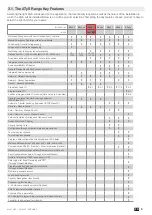
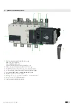
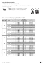
ATyS / ATyS r - 541630C - SOCOMEC
800 A
1000 A
1250 A
1600 A
2000 A
2500 A
3200 A
3 P
4 P
3 P
4 P
3 P
4 P
3 P
4 P
3 P
4 P
3 P
4 P
3 P
4 P
in
mm
in
mm
in
mm
in
mm
in
mm
in
mm
in
mm
in
mm
in
mm
in
mm
in
mm
in
mm
in
mm
in
mm
C
15.39
391
15.39
391
15.39
391
15.39
391
15.39
391
15.39
391
15.39
391
15.39
391
523
20.59
523
20.59
523
20.59
523
20.59
523
20.59
523
20.59
F
19.84
504
22.99
584
19.84
504
22.99
584
19.84
504
22.99
584
23.46
596
28.19
716
23.46
596
28.19
716
23.46
596
28.19
716
23.46
596
28.19
716
M
10.04
255
13.19
335
10.04
255
13.19
335
10.04
255
13.19
335
13.66
347
18.39
467
13.66
347
18.39
467
13.66
347
18.39
467
13.66
347
18.39
467
T
3.15
80
3.15
80
3.15
80
3.15
80
3.15
80
3.15
80
4.72
120
4.72
120
4.72
120
4.72
120
4.72
120
4.72
120
4.72
120
4.72
120
X
1.87
47.5
1.87
47.5
1.87
47.5
1.87
47.5
1.87
47.5
1.87
47.5
2.09
53
2.09
53
2.11
53,5
2.11
53,5
2.11
53,5
2.11
53,5
2.11
53,5
2.11
53,5
90°
90°
I
II
0
POWER
AUT
Ø 4 ... 8mm
PROG
OK
AUT
READY
TEST ON LOAD
TEST OFF LOAD
AT
y
S
g
Un
Auto Conf
5
1
10
14
5
1
10
13
0
1
5
10
20
60
0
1
5
10
20
60
G:
H:
E:
F:
REMOTE CONTROL
A: 3 Ph
B: 1 Ph
C: Neutral
D: Neutral
AT
y
S
Un
N°
PP / PN
1:
220 / 127
2:
380 / 220
3:
400 / 230
4:
415 / 240
5:
480 / 277
6:
208 / 120
7:
220 / 127
8:
230 / 132
9:
240 / 138
10:
380 / 220
11:
400 / 230
12:
415 / 240
13:
480 / 277
5
6
7
8
9
10
11
12
13
14
15
16
18
20
1:
2:
3:
4:
5:
6:
7:
8:
9:
10:
11:
12:
13:
14:
3
3
4
4
5
5
6
6
7
7
8
8
9
10
N°:
Δ
U
Δ
F
%
XXX
50
H
z
60
H
z
XXXXXXXX
Motorised Changeover Switch
1600A
Ref : 95054160
AUT
5.43
138
5.91
150
X
T
Fix. M
F
C
C
Fix
. 9.84
250
11.02
280
11.02
280
0.83
21
0.83
21
0.35
9
0.49
12.5
0.33
8,5
0.62
15,75
0.62
15,75
0.20
5
0.20
5
0.63x0.43
16x11
ø
0.35
ø 9
ø
0.59
ø 15
0.59
15
ø
0.49
ø 12,5
0.59
15
1.12
28,5
1.12
28,5
0.33
8,5
1.97
50
2.36
60
3.54
90
1.30
33
1.18
30
1.18
30
1.77
45
1.77
45
0.98
25
0.98
25
1.30
33
0.39
10
1250 A
1
2
30
1302
2
312 313 314 315 316 317 63A64A 24 14 04 13
CONTROL
OUTPUTS
1
2
2
1
3
3x
Ø 4-8 m
m
Contactor logic
Impulse logic
order I
position I
order 0
position 0
order II
position II
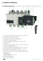
STEP 6A
Automatic Operation
Ensure that the emergency handle is not
inserted in the product and turn the mode
selector to the AUT position.
LED “Power” Green: ON
LED Manuel/Default: OFF
Non contractual document.
Subject to change without notice.
CORPORATE HQ CONTACT: SOCOMEC SAS 1-4 RUE DE WESTHOUSE - 67235 BENFELD, FRANCE - WWW.SOCOMEC.COM
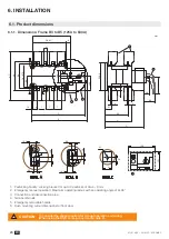
STEP 3
Dimensions
in.
/mm.
800 A to 1000 A
2000 A to 3200 A
800 A to 1600 A
1600 A
to 3200 A
ATyS Voltage
Sensing and
Power supply
Kit excludes the
need for fuses
F1 & F2.
Manual Operation
STEP 6B
Imp. ≥60ms
maintened
To enable control, close contact 312 with 317.
To force the product to 0 position/OFF bridge the contact
313 with 317. For contactor logic bridge contact 316
with 317. To operate: close the contact corresponding
to the desired position.
STEP 5
Check
Whilst in manual mode, check
the wiring and if ok power up the
product.
LED “Power” Green: ON
LED Manuel/Defaut Red
(Product not Available): ON
STEP 4
Ensure that the product is in Manual Mode.
CONTROL / COMMAND Terminals
Power Supply Terminal
Remove the Top cover to access and connect the terminal - Replace the cover before putting in service.
STEP 6C
Padlocking Mode
(as standard : in position O)
Connect the product with a cable of
section of 1,5 to 2,5 mm
2
.
Screw M3 - Tightening torque:
min.: 0.5 Nm - max.: 0.6 Nm
min.: 4.43 lbin - max.: 5.31 lbin
Содержание ATyS r
Страница 3: ...3 EN ATyS ATyS r 541630C SOCOMEC ...
Страница 26: ...26 EN ATyS ATyS r 541630C SOCOMEC 6 3 4 Terminal screens 125A to 630A 500A to 1600A 2000A to 3200A ...
Страница 41: ...41 EN ATyS ATyS r 541630C SOCOMEC 9 CHARACTERISTICS ...
Страница 51: ......