background image

Lit. No. 74256, Rev. 02 

12 

February 15, 2020

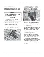
MOUNTING THE SPREADER

4.  Install the chute/de

fl

 ector assembly to the spinner 

assembly using the four 5/16" x 1-1/2" tapping 
screws and 5/16" locknuts in the supplied 
hardware kit to complete the drive assembly.

5.  Mount the drive assembly to the spreader using 

the 1/2" x 17-5/8" bent pin and secure it with the 
2-3/8" hairpin cotter. Ensure that the bent pin 
passes through the small center mounting tab on 
the auger drive enclosure.

6.  Slide the spreader forward until the de

fl

 ector/chute 

assembly makes contact with the vehicle. Then 
slide spreader back approximately 1" to allow 
proper clearance.

7.  Once the spreader is positioned front to back in 

the vehicle bed, center it left to right. 

8.  Looking at the inside corners of the spreader 

frame, you will notice four holes in the bottom of 
the frame. Using a paint pen or similar marking 
device, mark the hole locations on the vehicle bed.

If mounting holes cannot be drilled in the 
marked locations,

 install the mounting bars from 

the optional UTV mounting kit to the spreader 
frame using the supplied 1/2" x 1-1/2" carriage 
bolts and 1/2" locknuts. Use the existing holes in 
the mounting bars to mark drilling locations on the 
vehicle bed. 

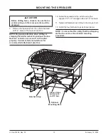
MOUNTING THE SPREADER

NOTE: Periodically throughout the snow and ice 
control season, verify that mounting devices are 
secure.

1.  Remove the tailgate from the UTV bed.

2.  Load the spreader onto the UTV bed.

3.  Assemble the chute to the de

fl

 ector using the 

four 1/4" x 3/4" serrated 

fl

 ange cap screws and 

1/4" locknuts in the supplied hardware kit.

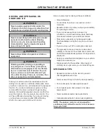
 WARNING

Spreader shall be bolted to vehicle frame. 
Do not rely on the tie-down chains or straps 
alone to hold spreader in vehicle.

 CAUTION

Before lifting, verify that hopper is empty of 
material. The lifting device must be able to 
support the spreader's weight.

De

fl

 ector

Chute

De

fl

 ector

Spinner 

Assembly

Содержание V-Pro 32200

Страница 1: ...UTV hopper spreaders with serial numbers beginning with 190901 and higher February 15 2020 Lit No 74256 Rev 02 SnowEx 531 Ajax Drive Madison Heights MI 48071 2429 www snowexproducts com CAUTION Read t...

Страница 2: ......

Страница 3: ...e Payload 11 Spreader Specifications 11 MOUNTING THE SPREADER 12 OPERATING THE SPREADER 14 Driving and Spreading on Snow and Ice 14 Spreading Tips 14 OPERATING THE SPREADER CAB CONTROL 15 Powering the...

Страница 4: ...Lit No 74256 Rev 02 4 February 15 2020...

Страница 5: ...esigned to spread snow and ice control materials only Do not use it for purposes other than those specified in this manual Register your spreader online at www snowexproducts com OWNER S INFORMATION O...

Страница 6: ...to alert against unsafe practices WARNING Indicates a potentially hazardous situation that if not avoided could result in death or serious personal injury NO STEP Slippery Surface When Wet May Cause S...

Страница 7: ...rely to truck body with bolt kit provided to prevent slipping or sliding Routinely check straps and handware to make sure they are secure D6548 Warning Label Read Owner s Manual Warning Caution Labels...

Страница 8: ...mes of spreading material CAUTION Disconnect electric and or hydraulic power and tag out if required before servicing or performing maintenance NOTE Lubricate grease fittings after each use Use a good...

Страница 9: ...lectrical components WARNING Vehicle exhaust contains lethal fumes Breathing these fumes even in low concentrations can cause death Never operate a vehicle in an enclosed area without venting exhaust...

Страница 10: ...2 13 1 2 20 16 2 18 5 33 3 36 9 59 1 36 5 72 2 126 200 67 0 94 6 105 6 144 3 162 7 11 4 13 1 23 6 26 0 41 8 47 5 67 0 74 8 102 1 115 2 M6 x 1 00 M12 x 1 75 M8 x 1 25 M14 x 2 00 M10 x 1 50 M27 x 3 00...

Страница 11: ...verloading could result in an accident or damage Do not exceed GVWR of UTV Follow the steps below to determine maximum volumes of spreading material CAUTION Never use wet materials or materials with f...

Страница 12: ...ame Using a paint pen or similar marking device mark the hole locations on the vehicle bed If mounting holes cannot be drilled in the marked locations install the mounting bars from the optional UTV m...

Страница 13: ...etals to aluminum bodies Galvanic corrosion can occur if not handled properly Contact vehicle manufacturer for recommended attachment practices Ratchet Strap Optional Mounting Bars Cross straps and se...

Страница 14: ...down and keep more space between you and other vehicles Slow down especially on higher speed roads Your headlamps can light up only so much road ahead If you are tired pull o in a safe place and rest...

Страница 15: ...owing nC no connection appears on the red status display for five seconds A single beep will sound Control enters standby mode with no lights illuminated If any button is pressed on the control it wil...

Страница 16: ...o wake Ready Mode Vehicle ignition is set to ACC or ON cab control is OFF Control has power Spreader is detected The Material Width and Material Flow control knobs can be set to start up conditions bu...

Страница 17: ...ule issue Contact authorized dealer EH Empty hopper beep will sound Check hopper for material Recalibrate Empty Hopper setting as described above for Cb code Lb Low battery Hopper module is sensing 10...

Страница 18: ...use may be driving down voltage Voltage is measured at the hopper module so Lb code may indicate cable voltage loss Check battery alternator and connections nC No connection Spreader not connected to...

Страница 19: ...d the EH code will flash on the display and a beep will sound whenever the hopper is empty The EH code is informational only and will not stop spreader operation Clearing Empty Hopper Calibration Data...

Страница 20: ...ighten all fasteners on spreader and mount FUSE REPLACEMENT If a problem should occur and fuse replacement is necessary the replacement fuse must be of the same type and amperage rating as the origina...

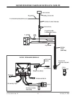
Страница 21: ...ga Shielded Twisted Pair Cable 6 ga Red 12 ga Black 6 ga Black 7 Pin Connector 50A Fuse 6 ga Red 18 ga Red To Vehicle Switched Accessory Vehicle Control Harness Vehicle Cable Assembly B PN XXXXX BAT G...

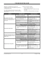
Страница 22: ...ntrol Codes table 1a See suggested solution in the Cab Control Codes table 1b Reset the control by pressing the ON OFF button 2 Poor electrical conditions 2a Clean or replace connectors 2b Apply diele...

Страница 23: ...rea on shaft and tighten locking bolt on side of auger 4 Auger runs backward 4a Check the wire connections at the P FEED N posts on the spreader module Auger harness RED to P FEED auger harness BLACK...

Страница 24: ...ipment when so altered without reference to illustrations or specifications used TrynEx International or the vehicle manufacturer may require or recommend optional equipment for spreaders Do not excee...

Отзывы: