background image

OBD-II/EOBD

OBD-II/EOBD Menu

57

If a test failed during the drive cycle, the DTC associated with that test is 
reported. If the pending fault does not occur again within 40 to 80 warm-up 
cycles, the fault is automatically cleared from memory.

Test results reported by this service do not necessarily indicate a faulty 
component or system. If test results indicate another failure after additional 
driving, then a DTC is set to indicate a faulty component or system, and the MIL 
is illuminated.

Refer to the 

Global OBD Vehicle Communication Software Manual

 for additional 

information.

Global OBD II Clear Codes

This option is used to clear all emission related diagnostic data, such as DTCs, 
freeze frame data, and test results, from the memory of the selected ECM. Although 
OBD-II/EOBD displays generic OBD-II/EOBD data only, clearing codes erases all 
of the stored data, including any enhanced codes and freeze frame information.

A confirmation screen displays when the clear codes option is selected to prevent 
accidental loss of data. Select to continue from the confirmation screen. Refer to the 

Global OBD Vehicle Communication Software Manual

 for additional information.

Readiness Monitors

This test checks the status of the readiness monitoring system. An OBD-II /EOBD 
control system runs continuous and periodic tests to check the status of emission-
related subsystems to gauge the integrity of the electronic operations. Two options 
are available for Readiness Monitors:

Monitors Complete Since DTC Cleared

—displays the status of all monitors 

that have run since the last time ECM memory was erased.

Monitors Complete This Cycle

—displays the status of the monitors that ran 

during the current drive cycle only.

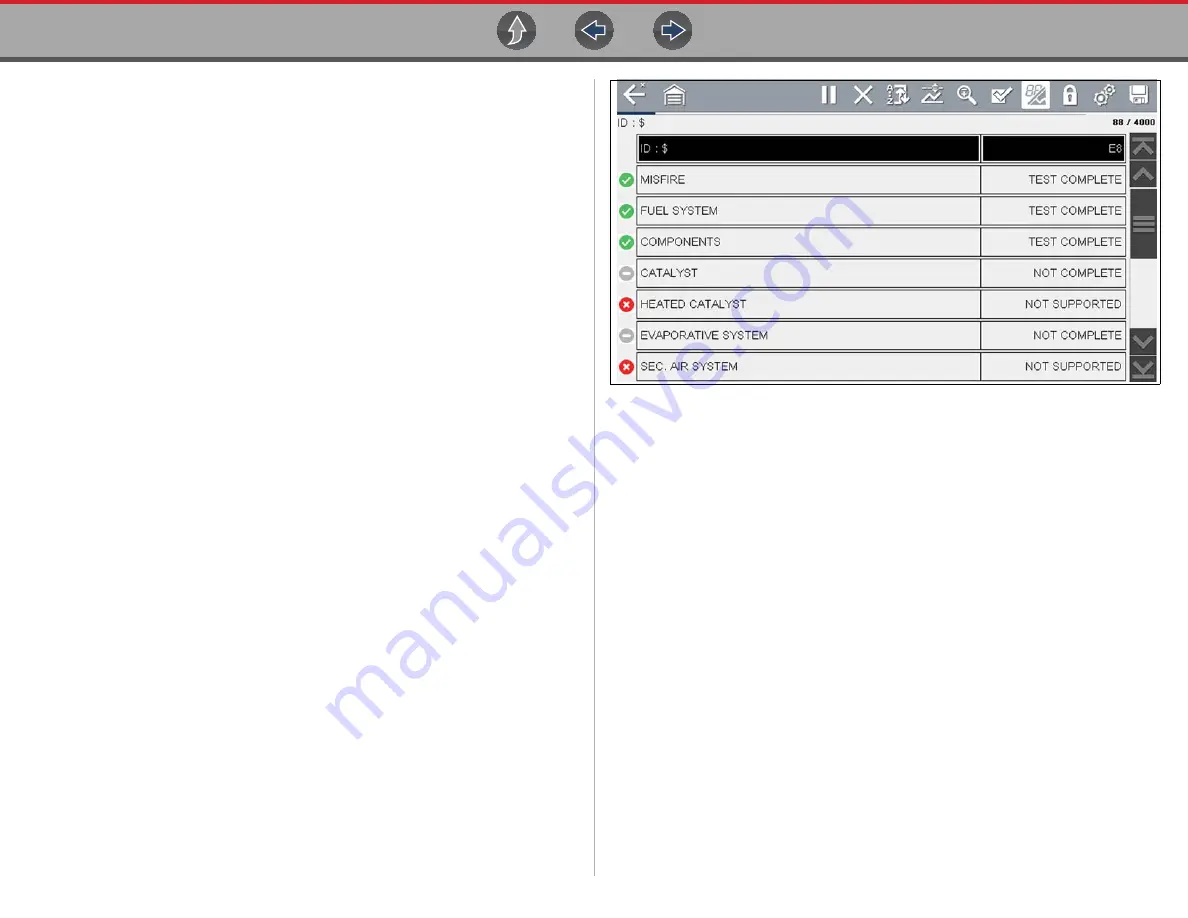
Selection of either option displays test results as shown in the data viewer 
(

Figure 8-3

).

Quick reference indicators are used to show monitor status on the left side of the 
screen (

Figure 8-3

):

Green icon “

a

” mark

 - Monitor test is complete

Gray icon “—” mark

 - Monitor test is not complete 

Red icon “X” mark

 - Monitor test is not supported by vehicle

Figure 8-3 

Readiness monitor test report

Use the scroll bar to view the entire list of Readiness Monitors.

Selecting 

Save

 from the toolbar saves the monitor data as an .SCM file for review 

at a later time. See 

View Saved Data

 on page 63

 for additional information.

MIL Status

This test checks the ECM commanded state (on or off) if the malfunction indicator 
lamp.

Содержание APOLLO D8

Страница 1: ...User Manual ZEESCGB333A Rev A Scanner Previous Vehicle and Data OBD II EOBD Tools Scanner Previous Vehicle and Data OBD II EOBD Tools Start...

Страница 2: ...eneral Information Maintenance OBD II EOBD Quick Reference Information Intelligent Diagnostics Table of Contents TOC Click a Topic Scanner Using Page Controls Tools Wi Fi Connection Snap on Cloud Basi...

Страница 3: ...tion 13 Scanner Overview 13 Scanner Starting Stopping 14 Features and Icons 14 Scanner Features 14 Scanner Control Icons 15 Basic Scanner Operation Quick Start 15 Vehicle Identification 16 System Main...

Страница 4: ...ork Advanced Connecting to a hidden network 76 Wi Fi Testing 76 Wi Fi Troubleshooting and Status Messages 77 Informative Messages 79 Section 12 Snap on Cloud 80 Key Features 80 Important Notes 80 Regi...

Страница 5: ...s and test procedures It is important to perform tests in an appropriate and acceptable manner that does not endanger your safety the safety of others in the work area the equipment being used or the...

Страница 6: ...l hazard Safety Message Example Risk of electric shock Prior to recycling the battery pack protect exposed terminals with heavy insulating tape to prevent shorting Disconnect all test leads and turn d...

Страница 7: ...presentative for availability of other functions and optional equipment Conventions The following conventions are used Terminology The terms Scanner and Scanner function are used to describe the Scann...

Страница 8: ...menu options Example Press the OK button Notes and Important Messages The following messages are used Notes A NOTE provides helpful information such as additional explanations tips and comments Examp...

Страница 9: ...t typical list shown below then select Connect Wi Fi Applications The following integrated Repair Information Application provides up to date service repair information directly to your diagnostic too...

Страница 10: ...d the AC power supply are located on the top of the diagnostic tool Figure 2 2 Top view 1 Battery Status Indicator LED 2 Power Supply Jack AC power supply connection 3 Mini USB Jack USB cable connecti...

Страница 11: ...Removing Installing the Battery Pack on page 98 Battery Pack Charging Battery charging occurs whenever the data cable is connected to a vehicle DLC Battery charging also occurs when the AC power supp...

Страница 12: ...upply Rating 15VDC 2A DC Operating Voltage 10 to 30VDC Width 11 06 in 281 0 mm Height 6 29 in 160 0 mm Depth 1 58 in 40 3 mm Weight including battery 2 65 lb 1 20 kg Operating Temperature Range ambien...

Страница 13: ...ou attempt to turn the diagnostic tool off while communicating with the vehicle Forcing a shut down while communicating may lead to ECM problems on some vehicles Never disconnect the Data Cable when t...

Страница 14: ...e is given 2 Y Accept Push type button To confirm a selection from a menu or program To select an item that was highlighted using the direction arrows To advance to the next screen in a series To answ...

Страница 15: ...formed Other information may include The identification ID of the test vehicle The name of the active menu or function The name of the test being performed Function Name Function Icon Description Scan...

Страница 16: ...layed The Up and Down directional buttons can also be used to move through the data one line at a time Press and hold a directional button to rapidly scroll through data Icon Function Icon Function Ba...

Страница 17: ...the vehicle There is a circuit fault in the data cable or adapter Incorrect vehicle identification was entered Refer to the Vehicle Communication Software manuals for manufacturer specific problems Me...

Страница 18: ...e the supplied DA 4 data cable 1 Connect the data cable to the diagnostic tool Figure 4 1 Figure 4 1 DA 4 data cable 26 pin end connection to diagnostic tool 2 After identifying the vehicle using the...

Страница 19: ...ith the vehicle then displays a list of available tests see Scanner on page 13 for additional information 4 1 1 Optional OBD II EOBD Data Cable A shorter 6 ft 1 8 m DA 4 OBD II data cable is available...

Страница 20: ...EOBD cable to the DA 5 adapter The DA 5 adapter connects to the manufacturer specific OBD I adapter This may be used instead of the optional OBD I data cable An optional OBD I data cable is available...

Страница 21: ...ontrol modules to access diagnostic trouble codes DTCs parameter data PIDs functional tests and more To navigate the application use your fingertip or the control buttons to make onscreen menu selecti...

Страница 22: ...ower down the diagnostic tool A warning message displays if you attempt to shut down while the diagnostic tool is communicating with the vehicle z To exit the Scanner function 1 From any active Scanne...

Страница 23: ...stant ID may occur See Instant ID on page 18 for additional information 5 If Instant ID is not supported after selecting vehicle make and year if needed choose Automatic ID or Manual ID and enter the...

Страница 24: ...he diagnostic tool See Data Cable Connection OBD II EOBD Vehicles on page 10 2 Turn the vehicle ignition switch on 3 Connect the data cable to the vehicle data link connector DLC See Data Cable Connec...

Страница 25: ...be made If this occurs proceed to Selecting Manual ID next Selecting Manual ID allows you to manually enter all the vehicle information to identify the vehicle b1 Follow the screen prompts to enter al...

Страница 26: ...identification process 6 After the vehicle has been identified the vehicle confirmation screen displays If the vehicle information is correct select OK to continue NOTE Depending on the vehicle Instan...

Страница 27: ...lues for certain components after making repairs Selecting opens a submenu These options are found on the Functional Tests Menu for some models System Tests provides specific subsystem testing Perform...

Страница 28: ...st Test Failed displays a complete list of failed tests Test Failed Since Code Cleared displays a list of tests that failed since the last time codes were cleared from ECM memory Clear Codes The diagn...

Страница 29: ...e s system main menu depending on the vehicle manufacturer displays the Data menu Figure 5 7 The Data menu displays the available PID lists based on the selected vehicle system Figure 5 7 Typical Data...

Страница 30: ...Misfire EVAP and Fuel Trim PID lists are related to the Engine system These special PID lists are basically custom PID lists that can save you time by allowing you to view a related set of PIDs when t...

Страница 31: ...sed for saved files Limiting the parameters also allows you to focus on any suspicious or symptom specific data parameters z To create a custom data list 1 Select the Custom Data List icon on the tool...

Страница 32: ...enu and then return to the Data Menu your Custom List is deleted Figure 5 15 Custom PID list cross system Some vehicles may support a cross system custom PID list which allows you to choose multiple P...

Страница 33: ...pecific data parameters z To create a Cross System custom data list 1 From the Data Menu select the Custom List icon on the toolbar Figure 5 16 The Custom List icon allows you to start a custom list d...

Страница 34: ...List however if you back out to the Main Menu and then return to the Data Menu your Custom List is deleted Figure 5 20 5 4 2 Data Views List Graph A typical Data screen is shown in Figure 5 21 This ex...

Страница 35: ...h view Changing Data Views List Graph Selecting the View icon Figure 5 23 opens a drop down menu of viewing options PID List 1 Graph 2 Graphs 4 Graphs The PID List view is a 2 column display with the...

Страница 36: ...ature allows you to position related parameters together making it easier to monitor their values and spot inconsistencies Locked parameters display as the top frames on the main body of the display s...

Страница 37: ...buffer memory reaches it s full capacity the data buffer will continue to store new data however earlier stored data will be removed to allow room for the new data being stored The most recent data is...

Страница 38: ...he cursor Red Triggered PID Activation Point When using triggers a vertical red cursor is displayed in the data of the triggered PID at the point where the trigger was activated When multiple PIDs are...

Страница 39: ...yed on all PIDs indicating where the data was paused Figure 5 31 Figure 5 31 5 4 7 Saving Data Files Saving data is useful when trying to isolate an intermittent problem or to verify a repair During n...

Страница 40: ...3 Toolbar control icons are described in Scanner Control Icons on page 15 and Common Toolbar Control Icons on page 8 The blue vertical cursor Figure 5 33 indicates your position in the data and is den...

Страница 41: ...e see ShopStream Connect on page 90 5 4 8 Using Zoom The zoom function allows you to change the magnification level of the graphed data during data collection and review Changing magnification levels...

Страница 42: ...e shown in Figure 5 36 Figure 5 36 1 Armed PID Trigger Indicator A blue outlined flag indicates the PID trigger is armed 2 Upper and Lower Limit Lines Armed Colored limit lines indicate the trigger is...

Страница 43: ...ger menu If triggers are already set the menu options are Clear Trigger deletes the highlighted trigger Disarm Trigger disarms the highlighted trigger Clear All Triggers deletes all set triggers 3 Sel...

Страница 44: ...across the designated graph Figure 5 40 Repeat this procedure to establish trigger points for other parameters up to three if desired NOTE Only three parameters can have trigger levels set at one time...

Страница 45: ...display in the menu There are several types of functional tests Information Tests these are read only tests like selecting VIN from a Functional Tests menu to display the VIN of the identified vehicle...

Страница 46: ...Scanner Functional Tests 38 Figure 5 44 Functional test example Figure 5 45 Functional test example Figure 5 46 Functional test example Figure 5 47 Functional test example...

Страница 47: ...organized into a series of diagnostic tips that are designed to quickly lead you to the root cause of a particular problem The tips are vehicle specific which means only tips that relate to the identi...

Страница 48: ...e 6 1 Vehicle System Report VEHICLE INFORMATION VIN JN8AS5MT0FW000000 MAKE Nissan YEAR 2016 MODEL Rogue ENGINE 2 5L L4 MFI QR25DE SYSTEM CodeScan LICENSE PLATE CODE SCAN RESULTS Systems Analyzed 10 En...

Страница 49: ...s and opens the Code Scan results screen Figure 6 3 Figure 6 2 NOTE Selecting Clear All Codes Read by Code Scan Figure 6 2 erases all DTCs from all vehicle system modules that were read by Code Scan S...

Страница 50: ...les and Data on page 62 To view print the report on the Snap on Cloud see Vehicle System Report on page 44 NOTE The code scan can also be saved manually by selecting the Save icon 6 1 1 Total Number o...

Страница 51: ...or a system in the list select the system then select the System icon Figure 6 5 Figure 6 5 System icon opens Main Menu Select the expand collapse icon Figure 6 6 on the left side of a system category...

Страница 52: ...stem Report that is uploaded and saved to your Snap on Cloud account if registered and connected Report examples are shown in Figure 6 1 Using the Snap on Cloud the report can be printed downloaded at...

Страница 53: ...he data you need related to the code Smart Data also highlights PIDs that are operating outside known good values Functional Tests and Reset Procedures Test components using command functionality dire...

Страница 54: ...ay Be Available indicates content may be available however you are not currently connected to the Web Services Network This message may be caused by a Wi Fi connection issue or you do not have access...

Страница 55: ...back to the previous screen The following descriptions are used with Figure 7 2 1 Wi Fi Connection Status Indicator A Wi Fi connection indicator cloud icon is provided on the top of the screen Figure...

Страница 56: ...ults Dropdown Menu The Code Results Dropdown menu allows you to quickly choose any of the scanned codes from the code list without having to exit Intelligent Diagnostics Select a code to view specific...

Страница 57: ...causes See example in Figure 7 5 cleaned mass airflow sensor Figure 7 5 Example Probable Cause within Top Repairs Graph 7 6 Smart Data Smart Data filters out all non relevant PIDs and shows you a cus...

Страница 58: ...tivated A blue outlined flag indicates the PID is armed and operating within it s limits trigger not activated PID trigger points upper lower value limits are automatically set using known good upper...

Страница 59: ...ure 7 10 Triggers activated 7 7 Functional Tests and Reset Procedures Selecting the Functional Tests and Reset Procedures card Figure 7 11 opens the Tests main menu Figure 7 12 which displays a list o...

Страница 60: ...lated Real Fixes that have been gathered from actual shop repair orders The Real Fix displayed on the Main Menu above the Real Fixes card is the most common Real Fix to date NOTE Fixes have been resea...

Страница 61: ...er card Figure 7 16 to view a list Figure 7 17 of code specific tips gathered from industry professionals NOTE Tips have been researched and obtained from professional automotive OEM and specialty tec...

Страница 62: ...Intelligent Diagnostics Troubleshooter 54 Figure 7 18...

Страница 63: ...t page 58 Connector Information page 61 Manual Protocol Selection page 61 Codes page 56 Pending Codes page 56 Readiness Monitors page 59 MIL Status page 59 Troubleshooter page 59 01 Display Current Da...

Страница 64: ...igure 8 2 The DTC results screen is similar to the same screen used in the Scanner function Figure 8 2 DTC Results Screen Codes The Codes option displays a list of current emission related DTCs OBD II...

Страница 65: ...Vehicle Communication Software Manual for additional information Readiness Monitors This test checks the status of the readiness monitoring system An OBD II EOBD control system runs continuous and per...

Страница 66: ...are displayed The diagnostic tool establishes a communication link with the test vehicle then opens an information screen Figure 8 4 Figure 8 4 Protocol information The information screen shows how m...

Страница 67: ...t vehicles covered by the vehicle communication software 01 Display Current Data Use this test to display the serial data transmitted by the selected vehicle electronic control module ECM The main bod...

Страница 68: ...06 On board Monitored Systems This option opens a menu of tests from the monitored systems The available data is for specific systems and components that the on board diagnostic system monitors conti...

Страница 69: ...hich one and how to connect it displays 4 Select Continue Information on where to locate the vehicle diagnostic connector displays 5 Select Continue to return to the System menu Manual Protocol Select...

Страница 70: ...ification of the last twenty five vehicles tested so there is no need to go through the complete vehicle identification sequence when performing a retest after repairs have been made The oldest vehicl...

Страница 71: ...tool and a PC See ShopStream Connect on page 90 To connect to a PC see Connect to PC File Transfer on page 67 NOTE A maximum of 50 files are displayed To view all if more than 50 files stored transfer...

Страница 72: ...scan XML file from the saved file list opens that file onscreen Figure 9 4 Figure 9 4 Typical Code Scan Results XML file viewed onscreen Select the Diagnose icon Figure 9 5 arrow to open Intelligent D...

Страница 73: ...displays Select the file s to be deleted using the checkboxes Use the Select All Deselect All icon as necessary 1 Select All Deselect All Icon 2 Delete Icon 3 Selected files to be deleted Figure 9 6...

Страница 74: ...tings page 71 Daylight Savings Time page 71 Time Format page 72 Date Format page 72 AUTO VIN page 72 Wi Fi Connection Troubleshooting page 74 10 1 Tools Menu The following options are available from t...

Страница 75: ...to register See section Snap on Cloud on page 80 for registration and operation instructions 10 1 3 Configure Shortcut Button This feature allows you to change the function of the Shortcut button Opt...

Страница 76: ...for poor lighting conditions Font Type on page 70 switches between standard and bold text for better visibility Backlight Time on page 70 adjusts how long the screen stays on with an idle diagnostic...

Страница 77: ...nd a please wait message momentarily displays followed by the Home screen The new toolbar setting is now active High Contrast Toolbar This option allows you to switch to a high contrast toolbar This t...

Страница 78: ...ete the touch screen calibration sequence once it has begun Never turn off the diagnostic tool while a screen calibration is in process z To calibrate the touch screen 1 Select Tools from the Home scr...

Страница 79: ...Select the up icon on the screen or press the up b button to incrementally increase the number in the highlighted field Select the down icon on the screen or press the down d button to incrementally d...

Страница 80: ...stant ID feature Configure Wi Fi Selecting Configure Wi Fi allows you to configure and troubleshoot the diagnostic tool Wi Fi connection see Section 15 on page 147 Configuring Scanner This option allo...

Страница 81: ...various units Figure 10 10 Configure units menu z To change the units setup 1 Select Tools from the Home screen to open the menu 2 Select Configure Units to open the menu 3 Select an item from the Con...

Страница 82: ...p page 75 Turning Wi Fi On and Connecting to a Network page 75 Add Network Advanced Connecting to a hidden network page 76 Wi Fi Testing page 76 Wi Fi Troubleshooting and Status Messages page 77 11 1...

Страница 83: ...oard and then select the check mark on the keyboard to continue Networks with a proxy challenge page or that require the user to accept terms of usage are not supported Wi Fi performance varies depend...

Страница 84: ...he type 4 Enter the network name or SSID 5 Enter the network password 6 Select Connect at the prompt to connect to the network 7 Select OK at the confirmation screen to continue using this connection...

Страница 85: ...ence as used in the following troubleshooting chart Router The data transmission device directly connected to your ISP Remote Wireless Access Point A wireless connection device between the router and...

Страница 86: ...networks have been deleted forgotten turn off the diagnostic tool 5 Turn on the diagnostic tool and connect to the desired Wi Fi network see Turning Wi Fi On and Connecting to a Network on page 75 Gen...

Страница 87: ...ause Displayed Tip Message Corrective Action Checks Hardware Wi Fi radio not responding and or will not turn off Contact Customer Support for assistance Wi Fi radio not responding and or will not init...

Страница 88: ...key name to help you organize and search report files Use the Search function to quickly find files by Tag Description and Title 12 2 Important Notes To use the Snap on Cloud account setup and diagnos...

Страница 89: ...select Save when done 10 Log out of Profile Manager then select the ALTUS Home Page browser tab to get started 11 Turn the diagnostic tool off and then on 12 See Using the Snap on Cloud Your Diagnosti...

Страница 90: ...your device Alternate Method open the file in a new browser tab see File Detail Tags on page 84 and use the browser viewer tools to print the file Note All browsers may not support this feature Sharin...

Страница 91: ...orts are displayed with the most recent uploads at the top The Report upload date is displayed at the upper left The date is shown once at the top of the series of reports scroll up down to see all fi...

Страница 92: ...d as desired 3 Your Account Username and timestamp See Account on page 87 for additional information The timestamp indicates the date time the file posted 4 Description user entered searchable text En...

Страница 93: ...Figure 12 10 2 Select Copy to Clipboard Figure 12 11 from the pop up window Figure 12 11 3 Open your e mail text social media etc app and paste the URL into a message to share with others The URL link...

Страница 94: ...ssigned or user assigned Known Good Bad Checkboxes selecting a checkbox automatically creates a searchable tag e g good or bad Description user entered text Tag user entered text See File Detail Tags...

Страница 95: ...ile Manager you must select the ALTUS Home Page browser tab Enter your Username and Password at the Login screen Profile Manager includes five tabbed categories to help you manage your account informa...

Страница 96: ...stic tool or Diagnostic Tool Enter the device Serial Number serial number of the device PIN specific PIN associated to the device Code authorization code specific to the device Device Name user define...

Страница 97: ...Snap on Cloud Using the Snap on Cloud 89 Logging Out To log out select Profile from lower toolbar then select Logout Figure 12 21 Figure 12 21...

Страница 98: ...uals Main Topic Links Using SSC Connecting to your PC page 90 SSC Main Screen page 91 Scanner DataViewer page 92 Image Viewer page 92 Printing the Code Scan Vehicle System Report page 93 Customizing t...

Страница 99: ...editable 2 File directory structure displays the file directory structure of your PC in standard Windows format and shows any connected diagnostic tools at the bottom of the data list 3 Data Manager...

Страница 100: ...eenshots saved on your diagnostic tool with your PC NOTE File extension types vary depending on the diagnostic tool Not all the file extensions described here may be available on your diagnostic tool...

Страница 101: ...ct 1 Double click the code scan XML file from the file list to open the Vehicle System Report Figure 13 5 in the Code Scan Viewer Figure 13 6 Figure 13 5 2 Select Print or Print Preview from the Code...

Страница 102: ...p Info dialog box opens Figure 13 9 allowing you to enter the name address and phone number for your shop This information is included as a header on the report Figure 13 9 A preview panel at the bott...

Страница 103: ...are available free of charge and are provided as necessary to update installed software When your diagnostic tool is connected to a PC using SSC the SSC software will automatically check for updates a...

Страница 104: ...ent is available at https eula snapon com diagnostics To Accept at the screen prompt Figure 13 13 click the checkbox on the left side of the window and then select Agree and Continue The software will...

Страница 105: ...with a damp cloth IMPORTANT Do not use any abrasive cleansers or automotive chemicals on the diagnostic tool 14 1 1 Cleaning the Touch Screen The touch screen can be cleaned with a soft cloth and a mi...

Страница 106: ...loss of capacity due to self discharging If long term storage of the battery pack is necessary it should be stored in a in a cool dry well ventilated place with a 30 to 75 percent state of charge to p...

Страница 107: ...does contain recyclable materials If shipping is required ship the battery pack to a recycling facility in accordance with local national and international regulations IMPORTANT Always dispose of mat...

Страница 108: ...training videos are available on our website Follow along and learn the basics of diagnostic tool operation with our free training videos Videos are product specific and are available at http diagnost...

Страница 109: ...Tips Videos examples Air Fuel Ratio Sensor Test Fuel Injector Voltage and Current Tests Scope Alternator Ripple Test Scope Fuel Pump Current Ramp Test Scope BMW Rain Sensor Calibration Harley Davidson...

Страница 110: ...The Power of Troubleshooter Tips Scanner Ford 6 7L Transmission Solenoid Characterization Top Level Menus Built In Scope Training Ford Diesel Injector Coding Toyota EVAP Test VW Audi Flexible Service...

Страница 111: ...thin this manual may not be applicable to other diagnostic software versions Disclaimer of Warranties and Limitation of Liabilities All pictures and illustrations shown are for reference purposes only...

Отзывы: