background image

Print Results

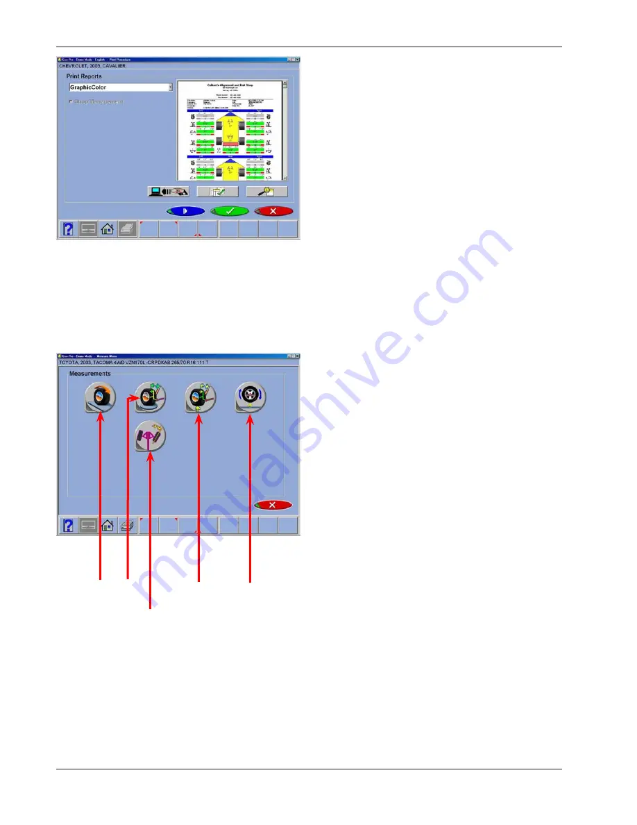
Select  Print  on  the  toolbar  (F4)    on  either  the  Front 
or  Rear  Readings  screen  to  go  to  the  Printer  Menu 
screen. The options are:

1-Select  Desired  Alignment  Report  -

  Select  the 

desired  type  of  report  to  be  printed  from  the  drop 
down box 

2  -  Import  from  a  disk  -

  This  selection  allows  a 

customized report or logo to be imported to the system 
directory.  Custom reports must be created by Crystal 
Reports*  by  the  user  or  authorized  agent. A  custom 
“BMP” logo can be imported as well.

3 - Set Default Report -

 Determine the desired report 

to be used as default and for one click printing.

4 - Zoom - 

Select this button to enhance the size of 

the displayed report. Click OK to continue printing or 
Cancel to go back to the print menu.

Measurement Menu

When the Measure icon is selected from the 
Home  Screen  or  from  the  toolbar  on  any 
readings screen, a screen appears that allows 
the operator to measure any wheel alignment 

angle.  The icons on this screen are defined 

in, and are explained below:

1.  4 Wheel Positioning

  –  repeats the Runout 

Compensation  process  that  locates  the 
vehicle spindles.

2.  Measure  Caster/SAI

  on  Turn  Plates  –  

accesses the steering angles measurement 
screen used to measure caster, SAI, 

3.  Measure Caster/SAI Elevated

  –  measure 

the  Caster  and  SAI  angles  with  the  wheels 
elevated (unloaded)

4.  Single Wheel Positioning

  –  instead of the 

normal compensation sequence, the vehicle 
can  be  jacked  to  allow  each  wheel  to  be 
compensated independently.  This is useful if a 
wheel must be removed during the alignment, 
for example to install a shim in the rear.

5. 

Maximum Turns

 is selected to measure the 

amount of steering angle to the right and to 
the left.


42

Operation


4


5

Содержание EEWA717A

Страница 1: ...Form ZEEWA717A Operators Manual EEWA717A and EEWA719A Aligner Systems ...

Страница 2: ...Blank page ...

Страница 3: ...ent basic safety precautions should always be followed including 1 Read all instructions 2 Care must be taken as burns can occur from touching hot parts 3 Do not operate equipment with a damaged power cord or if the equipment has been dropped or damaged until it has been examined by a qualified serviceman 4 Do not let cord hang over edge of table bench or counter or come in contact with hot manifo...

Страница 4: ...are no user serviceable items within the console other than the keyboard and printer Service on the unit must be performed by qualified personnel Do not open any part of the console other than noted areas Turn power switch off and unplug the unit before servicing Contact with high voltages can cause death or serious injury Risk of eye injury Debris dirt and fluids may drop from vehicles Knock off ...

Страница 5: ...ehicle Do not bypass any jack manufacturer s safety features Read jack manufacturer s operation instructions carefully Follow jack manufacturer s safety recommendations Improperly used or maintained jacks can cause injury Risk of burns Do not touch hot exhaust systems manifolds engines radiators etc Wear gloves whenever performing a service near hot components Hot components can cause burns Risk o...

Страница 6: ......

Страница 7: ... Clamps 10 Measuring Pods 10 Aligner Software 10 Screen Layout and Navigation 11 Toolbar Buttons 13 Setup Preferences 15 Preferences Screen 15 Interaction 16 Security 16 Units 16 Resolution 17 Angle Units 17 Linear Units 17 Loading Units 17 Pressure Units 17 Connectivity Options 18 Romess Inclinometer 18 Store Name 18 Regional Settings 19 Languages 19 Specifications 19 Shutting Down the Computer 2...

Страница 8: ...ing Customer Information 30 Selecting a Stored Record 30 Adding a New Customer 30 Editing an Existing Record 31 Backup and Restore 31 Charging the Pods 32 Powering the Pods 32 Runout Compensation 33 Left Rear Runout 34 Front Wheel Compensation 35 Lower Wheels and Bounce settle the Suspension 35 Readings Screen 36 Rear Readings Screen 37 Readings Toolbar Buttons 37 Aftermarket Products 38 Default P...

Страница 9: ...45 Toe Out on Turns TOOT 46 Maximum Turn Angle Lock to Lock 47 Adjust Menu 48 Adjust Caster and or Camber 48 Adjust Rear Camber Elevated 51 Adjust A Arms 52 EZ Toe 53 Shims and Kits 54 Default Part Vendor 54 INFO 54 Offset Cams and Bushings 55 Maintenance Menu 56 Calibration 57 Calibration Utilities 60 Calibration factors 62 Calibration history 62 7 ...

Страница 10: ...d when performing alignments All standard alignment features are activated at manufacture Advanced features when available are activated as they are purchased with Activation Codes Setups for the PC hardware and Microsoft Windows are preset at the factory to maximize performance and should not be altered Aligner Location Locate the aligner in a location that provides the most convenience for the o...

Страница 11: ...ose the aligner or measuring Pods to water heavy dust environments or operations that produce metal chips Do not block the rear of the computer or disable the cooling fan Computer Connections Installation of the aligner includes connection of devices to the computer Care should be taken if there be any reason to examine those connections or change a component such as the pointing device Note Refer...

Страница 12: ... the keypad to become familiar with the layout of the Pod controls which are 1 Battery condition Front Runout indicator LEDs 2 On Off 3 Runout 4 Diagnostics LEDs 5 Master reset not shown Aligner Software Operation from the console is accomplished primarily by a single mouse click to initiate each function The right mouse button is not utilized within the alignment software A standard keyboard is i...

Страница 13: ...abs move to other major areas of aligner operation Each tab contains a new set of Function Icons to perform functions related to the title on the tab 3 Status Bar contains aligner setup and information on the vehicle selected 4 Radio Buttons enables the selection of one item among a list Click on the button to the left of the description to enable that function 5 OK and Cancel Buttons most screens...

Страница 14: ...n either vertical or horizontal clicking on the arrow moves the screen view in that direction to show additional selections or information You can also click and hold the center slider and move it up or down to create large movement 8 Function Icons when the pointer is positioned over any function icon a text pop up appears describing its function When the left mouse button is clicked this functio...

Страница 15: ...een Adjust from any readings screen launches the Adjust features Animation launches help with performing angle adjustments Zoom makes the selected meter fill the entire screen Unzoom returns from a zoomed meter to the standard meter screen Custom Specifications when selecting a vehicle brings up any custom vehicles that have been saved Restore OEM during editing of specs returns to OEM values Plus...

Страница 16: ... Recall the Customer record that is currently stored in memory Clear All Fields Select this button to clear all fields within the data file currently open Pod Voltage This displays a screen showing values critical for proper cordless operation Recall the Current Alignment Displays the current alignment stored values Toggle Editing Mode Select this button to toggle the method of editing a displayed...

Страница 17: ...red before the alignment process begins or any time thereafter Preferences Screen The Preference Screen allows access to the following setup selections each identified by an icon 1 Interaction controls several functions which alters interaction between the software and the user 2 Units selects the units to be displayed for angle and linear measurements 3 Connectivity activates access to a shop man...

Страница 18: ...Units icon from the Preferences tab Click on the radio button next to the desired selection of units of measure Once a prescribed unit of measure has been chosen all readings and specifications will be stated in those units on all readings screens Toe Units move the pointer over the toe units best suited to the operator s requirements and highlight the button left of the desired unit The choices a...

Страница 19: ... than when using the 0 01 degree setting Aligning the car to within hundredths of a degree requires a greater degree of precision on the technician s part to obtain exact readings Angle Units Specify the units in which all angular measurements will be displayed such as caster camber SAI included angle thrust angle etc Examples Degrees Decimal 0 5 degrees Degrees and Minutes 0 30 Inch Fractional 1 ...

Страница 20: ...nclinometer This menu is also where the Romess Inclinomenter is activated for use with certain makes of vehicles Mercedes Benz for example NOTE Not available Store Name Information entered into the Store Name selection will be utilized on the alignment results printout Several lines of information is available for printing The name of the business address city and state are entered Also available ...

Страница 21: ...he pointing device to move to down click to select Select OK when both screen and alternate languages are highlighted All screens will now be in the chosen language English is the first selection on both lists should it become necessary to change the unit back to the default setting Selecting Ctrl Alt F8 toggles to the Alternate language Specifications The specification tab allows for changing the...

Страница 22: ...located in the lower left corner of the Advanced Main Menu screen and in the tool bar of the Basic Menu screen 3 Answer Yes when prompted the computer system will then shutdown automatically From the Windows desktop 1 Close any programs or windows that may have been opened 2 Click the Start button and then click Shut Down 3 On the Shut Down Windows box that appears select Shut down the computer Cl...

Страница 23: ...turntables Raise the lift to a solid level lock position 4 Inspect the tires for any signs of abnormal wear tires often reflect any misalignment conditions 5 Perform a thorough component inspection Replace defective parts prior to performing the alignment Always check tire pressure and ride height 6 Mount targets and pods to the vehicle wheels Use the safety straps in the event of grip failure 7 P...

Страница 24: ...rack lift 4 Position the turntables as needed to insure the tires will be centered 5 Drive the vehicle forward onto the center of the turntables Alternative Method This method extends turntable life due to relief of load and stresses encountered when the brakes are applied or acceleration on a FWD vehicle 5A Place the vehicle in neutral release the parking brake and pull or push the vehicle forwar...

Страница 25: ...l clamps The clamps should be installed in a straight up vertical manner Use the mounting method that provides the greatest security to keep the target or pod from falling off the wheel Most wheels can be grabbed from the outside in by placing the claws between the bead of the tire and the outside edge of the rim Use the following steps 1 Extend the clamp outward to a size larger than the rim by t...

Страница 26: ...wing steps 1 Extend the clamp inwards to a size smaller than the rim by turning the knob clockwise 2 Place the lower claws on the wheel lip at the bot tom of the wheel If a wheel weight is in the way move the clamp slightly to clear the weight It is not necessary to be perfectly vertical 3 Tighten the clamp by turning the knob counter clockwise until the upper claws engage the rim Continue to tigh...

Страница 27: ...gnment is currently in memory the user is directed to perform compensation then readings are displayed with no reference to specifications 3 Home returns the software to the opening Home screen as shown here 4 Print accesses the print report menu 5 Preferences access to various setup parameters to tailor the system to the users tastes 6 Maintenance Opens the maintenance menu for service and calibr...

Страница 28: ...r and Model Note The order the manufacturer year and model appear will vary depending on how the specifications are set up see Setup Vehicle Manufacturer or Make This screen shows the vehicle manufacturers in specification database The vertical scroll bar on the right indicates there are additional choices further down the page Click on the down arrow on the scroll bar move down Using the down arr...

Страница 29: ...rrow key to expand out the years this model was made Vehicle Model Use the direction keys or pointing device to select the model of the vehicle then select OK press Enter or double click the selection Custom Specifications Alignment specifications that have been added by the operator reside in a special database To retrieve these specifications go to the Vehicle Manufacturers screen and select Cus...

Страница 30: ...cal Bulletin has been issued that alters manufacturer s specifications Pressing Ctrl Alt F8 simultaneously allows specs to be viewed at any time from within the alignment process Editing Specifications To edit the displayed specifications click on toolbar button F11 Edit Specifications The toolbar configuration will change with a plus and minus sign displayed F6 and F7 Use the pointer to click on ...

Страница 31: ...rmation is requested by clicking on the icon associated with the assistance These icons are Adjustment Instructions Adjustment instructions are provided by selecting the first of three function buttons on the Animation screen Parts Required The center selection displays parts required to complete the alignment process parts such as shims eccentrics or other aftermarket supplied parts The displayed...

Страница 32: ...an be sorted and retrieved in several different ways drill down through data records sort alphabetically by last name by telephone number vehicle license plate number vehicle VIN number by date or by listing of all records Once the desired record is visible clicking on the plus sign expands the list to bring up a particular data set When selecting alphabetically select the first letter of the cust...

Страница 33: ... is saved when OK is entered Backup and Restore Datafiles can be backed up for security and restored upon demand The Datafiles are backed up from the Maintenance menu Using the Database Outside the Aligner Platform The database is stored on the hard drive in a file calledAlignmentData mdb This database file is compatible with several common database programs such as MicrosoftAccess not supplied Se...

Страница 34: ... Pods remain connected to the charge cord after receiving a full charge The state of charge LEDs will begin flashing indicating the level of charge As the Pods are discharged the LEDs will show the amount of remaining charge as shown to the left If only one LED is illuminated and flashing less than 10 power remains indicating the unit must be charged Powering the Pods Turn Pods On by momentarily d...

Страница 35: ...TE If the display monitor is not visible for position indication watch the blinking LED s on the Pod during runout As each of the four positions are initiated the runout indicator LED begins blinking slowly The blink will increase in speed as the proper position is approached The LED will stay on continuous when the proper position is achieved When runout has been measured the LED will again begin...

Страница 36: ...lamp will be down as indicated in the illustration to the left C Rotate the wheel in the same direction to the 3 o clock position The top of the clamp will be to the right as indicated in the illustration to the left B Rotate the wheel in the same direction to the 12 o clock position The top of the clamp will be up as indicated in the illustration to the left Repeat the above steps for the Right R...

Страница 37: ... o clock position until pr tinue D Repeat the above steps o Lower Wheels and Bounc Suspension The next screen that appea technician to lower the whee or settled the suspension so at a true ride height Slip pl utilized to provide the nece required to return the vehicl resting position After runout compensation prompted to lower the whee suspension and press OK to LEDs will flash during Runout 35 ...

Страница 38: ...in front of each wheel after a caster swing is performed The numeric value for caster is directly above the meter When a meter is green the reading is within specifications When the arrow is centered within the green it is at the preferred value Ared meter indicates the reading is out of specification The red meter contains a green band indicating the direction of needed change A gray meter indica...

Страница 39: ...alues Readings Toolbar Buttons Buttons available on the Readings Screens toolbar from left to right are F1 Help displays operation assistance for the screen presently open F3 Home returns the software to the opening Home Alignment tab F4 Print accesses the print report menu F5 Measure access to measuring additional angles F6Adjust access to assistance for the technician with angle corrections F7An...

Страница 40: ...rection required Highlight one of the part numbers displayed then click on the Info ICON to invoke a screen describing the correct orientation of shims or other corrective aftermarket parts The Info ICON can be selected from several places of the screen If highlighted information is available Click the Aftermarket Tools Available ICON to view tools required for the specific procedure if available ...

Страница 41: ...portant on many vehicles for proper handling The numeric value between the left and right toe meters indicates the rear Total Toe sum of individual toe Level and Lock Steering Wheel Before front readings are displayed it is necessary the level the steering wheel and lock it in place using the steering wheel holder Once these steps are completed press OK to move forward 39 ...

Страница 42: ...urements are within specification the center portion of the meter is green If red is displayed the readings are outside of specifications Grey meters indicate this angle has no specification Elevated camber and caster readings can be viewed by selecting the Jack icon located right of the cross values NOTE Front Readings Toolbar buttons are explained in the Rear Readings section NOTE If a screen or...

Страница 43: ...ormation below Click on the down arrow of the scroll bar to reveal Front and Rear Diagnostics values if measured After readings have been observed other measurements or adjustments may be required for completion of the alignment process Determine additional measurements 1 or adjustments 2 or select other features to complete the process Other features are Return to Home Print Results Measure Adjus...

Страница 44: ...t Menu When the Measure icon is selected from the Home Screen or from the toolbar on any readings screen a screen appears that allows the operator to measure any wheel alignment angle The icons on this screen are defined in and are explained below 1 4 Wheel Positioning repeats the Runout Compensation process that locates the vehicle spindles 2 Measure Caster SAI on Turn Plates accesses the steerin...

Страница 45: ...d wheel 2 Raise the front or rear axle being positioned as instructed Notice that VODI shows which wheel has been selected 3 Following the on screen graphics rotate the pod or target back approximately as directed by the indicator 4 When complete an instruction screen appears reminding you to lower the vehicle This is only necessary when all wheels that need to be positioned individually have been...

Страница 46: ...cons are displayed across the top of the screen Three icons for right turn measurements Three icons for left turn measurements and a center steering wheel icon The icons indicate the steering positions for measuring caster and steering axis inclination SAl simultaneously toe out on turns TOOT and maximum steering angle 44 Operation ...

Страница 47: ...the stop sign disappears when the measurement is complete 3 If only caster SAI is desired turn the wheel the opposite direction The software senses this action and places a red status bar above the caster SAI icon on the opposite side Follow the arrows to a 10o turn on that side A stop sign appears at the proper spot hold the wheel steady 4 When the green box and depressed icon appears the measure...

Страница 48: ...l the green box depressed icon appears and the stop sign disappears indicating completion of the measurement 4 To measure toe out on turns on the other side turn the wheel the opposite direction Note that the status bar appears over the caster SAI icon first It is always required to measure caster SAI before TOOT 5 Turn to the Caster SAI position When completed the red status bar appears over the ...

Страница 49: ...surement is completed 3 To measure maximum turn angle on the other side begin to turn the wheel the opposite direction Note that the status bar appears over the caster SAI icon first It is always required to measure caster SAI then toe out on turns before maximum turn angle 4 Perform caster steps and toe out on turns steps then continue turning out to measure at full steering lock 5 Hold steady un...

Страница 50: ...e angles including elevated adjustment adjustment on turn plates and adjustments that include toe angles 2 AdjustA Arms for vehicles whose caster and camber adjustments are located on the suspension A Arm this selection allows both angles to be corrected simultaneously 3 EZ Toe this software routine is a method of setting front toe making it easier to obtain straight steering wheels 4 Rear Shims a...

Страница 51: ...d this mode is used for adjusting Caster Camber and Toe on the front wheels The readings on the turntables are retained even though the wheels are elevated 3 Adjust Front Camber and Toe Only Elevated this mode is used for adjusting only camber and toe on the front wheels The readings on the turntables are retained even though the wheels are elevated It is not required to have a valid caster value ...

Страница 52: ...n as an eccentric cam is turned As the adjustments are made the meter movements and numeric values change The meters are color coded to show the readings relationship to specification Once the adjustments are completed press OK Post adjustment instructions will be displayed Unlock the brakes Press OK The software automatically returns to the readings screen where you started 50 Operation ...

Страница 53: ... elevated while retaining the measured camber values This gives the ability to make accurate correction of camber without vehicle weight inhibiting the adjustment process This would be useful for tapping down a wedge on a strut vehicle The adjustment screen displays live caster camber meters and numeric values for the left and right wheels along with live toe values Make the desired adjustments wh...

Страница 54: ...for the location of the adjusters It does not matter whether the a arms have shims slots or cams Select the proper icon on theAdjustA Arm screen The icons are Adjustment on Upper or Lower Control arm Adjustment on Turntables or Elevated The adjustment screen contains a graphic of the right side a arm along with two meters These meters represent the movement of the front and rear of the a arm and t...

Страница 55: ...ber 2 Select the EZ Toe icon from the Adjust screen 3 Level the vehicle steering wheel Select OK 4 Steer the right wheel to the adjust position Select OK 5 The next screen shows a meter indicating the amount of toe change needed for the right wheel 6 Adjust the right tie rod until the meter needle is in the green Select OK after completion 7 Follow the same procedures for the left wheel 8 Select O...

Страница 56: ...he screen to the left will be displayed Default Part Vendor Determine the desired part vendor to select as the default aftermarket supplier This selection will vary location to location and upon the Technicians preferences INFO The correct part number is automatically selected and displayed dependant on the vehicle selected and the amount of correction required Highlight one of the part numbers di...

Страница 57: ...insures the correct amount of caster and camber is obtained from the sleeve insert The calculations assume the current sleeve insert is a ZERO no offset If it is not examine the slot orientation to determine if the previous installation corrected camber or caster Enter the value of the old sleeve insert in the box below either caster or camber whichever most accurately reflects the orientation of ...

Страница 58: ... 2 Diagnostics primarily for service personnel this allows access to measuring Pod direct output 3 DemoMode Usedbyasalesrepresentative to demonstrate basic operation of the aligner Not used for actual alignments NOTE All screens will say Demo Mode when this feature is active 4 Windows Utilities Allows access to the Windows Desktop and also allows the operator to perform routine installation of pri...

Страница 59: ...ignment rack to a comfortable working 1 height From the Main Menu select the Maintenance Icon 2 Select the Calibration button from the Maintenance 3 menu Selectthe PodCalibration buttonfromtheCalibration 4 menu A Warning messageappearsinstructingtheuserthat 5 the calibration process should be performed by trained individuals Click on OK to continue 6 Place the calibration bar and stands calibratio...

Страница 60: ...8 so that the boom faces the rear of the rack Place the right pod on the calibration 9 bar so that the boom faces the rear of the rack Place the targets on the front turn plates 10 and orient the so that they are facing the pods It will be necessary to leave the targets mounted to the wheel clamps Select the appropriate rack for calibration 11 Rack A Rack B or Floor WiththePodslockedonthebarrotate...

Страница 61: ...od 2 points towards the rear of the rack Theunitwillprompttheusertorotatethebarsothatthetargetsrotated 3 forward 25 A stop signal will appear After the information is taken the user will be prompted to rotate the 4 targets 25 backwards from vertical When the calibration is complete the user will need to press OK 5 button to store the calibration data CALIBRATION COMPLETE 6 ...

Страница 62: ...ed to marry a set of exchanged pods to an alignment system Select the Pod Identification button The user is instructed with a WARNING that this process should be performed by trained individuals Click on the OK button to proceed Make sure that the pods to be identified are powered up and ready to be located If multiple aligners are used in the shop it is not necessary to power them down to complet...

Страница 63: ...t a pod number and ask the user if the LED s on any of the pods being married are flashing Look at both pods If the LED s on any of the pods are flashing click on OK If the system does not locate 2 pods the user is instructed to power down both pods and press the scan button again If after 3 attempts the system does not locate the pods it will be necessary to call technical support to generate the...

Страница 64: ...ibration to the next If either a Pod or Target shows a significant jump or drop on the History line it may indicate a catastrophic failure such as a drop to either a Pod or a Target or it may indicate that an incorrect calibration was done at that time Select the Calibration History button from the 1 calibration menu Using the Radio buttons on the left side of the screen 2 choose LF RF LR or RR Th...

Страница 65: ...Notes ...

Страница 66: ...o change without notice Equipment Services makes no warranty with regard to this material shall not be liable for errors contained herein or for incidental consequential damages in connection with furnishings performance or use of this material This document contains proprietary information which is protected by copyright and patents All rights are re served No part of this document may be photoco...

Отзывы: