


41
of
84
4. Once all connections are made, test system as follows:
a.
Light System
-
Lift must be fully collapsed
. Start raising lift. At approximately 30”
from the ground, the lights will illuminate. If not, please check that the 4mm polytube
connections are correct as they may be reversed.
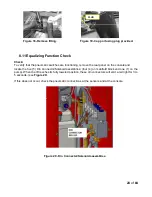
Comparable to the Upper Limit System (see
Section 8.8
), the Light kit is turned on by a
similar method. This system will have its own Cam and Sensor, located on the upper
hinge at the front right side runway.
NOTE:
Unlike the Upper Limit System, this system is not adjustable and is factory set.
Figure 35
b.
Locking System
- On front of console, switch the Slip Plate lever to “Unlock”. All
locking plates should be free to move, please verify. Now switch the lever to “Lock”, all
locking plates should be centered and locked, please verify. If not, check that all
polytube connections are correct and there is 90-120 psi of air pressure.
SWITCHING
POINT
Содержание EELR587A
Страница 7: ...7 of 84 3 0 SAFETY WARNING DECALS...
Страница 18: ...18 of 84 Figure 8 Hydraulic Connections...
Страница 22: ...22 of 84 TO LEFT DECK ASSEMBLY Figure 11 Air Safety Auxiliary Air Connections...
Страница 26: ...26 of 84 Figure 15b Optional LED Driver Box Circuit Connections...
Страница 35: ...35 of 84 Figure 28 Filler Angle Installation...
Страница 64: ...64 of 84 20 0 ACCESSORY ASSEMBLY 20 1 Front Turnplate...
Страница 67: ...67 of 84 20 3 Airline Routing for Locking Turnplates and Rear Slip Plates...
Страница 79: ...79 of 84 22 0 POWERPACK ASSEMBLY 22 1 Powerpack Assembly EAA0441V72A...
Страница 83: ...83 of 84 APPENDIX Foundation Plan...


