


23
of
84
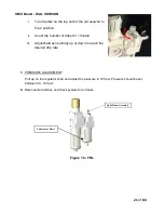
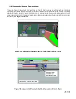
8.8 Pneumatic Sensor Connections
There are three (3) pneumatic limit switches on this lift. Each runway is outfitted with an individual
equalizing pneumatic switch mounted on a bracket located under the front of the runway. The third
pneumatic switch, used for height limit detection, is located under the rear slip plate area on the left
scissor assembly. Each Pneumatic Switch has a Ø4mm air supply line (Red) and a Ø4mm air return
line (Blue). See
Figure 12a & 12b.
Figure 12a - Equalizing Pneumatic Switch. (View under LS Deck - Front)
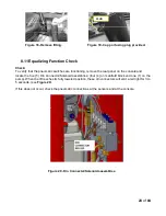
Figure 12b - Upper Limit Pneumatic Switch. (View under LS Deck - Rear)
HEIGHT LIMIT
SENSOR W/
ROLLER LEVER
REAR SLIP PLATE SECTION
Содержание EELR587A
Страница 7: ...7 of 84 3 0 SAFETY WARNING DECALS...
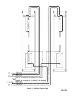
Страница 18: ...18 of 84 Figure 8 Hydraulic Connections...
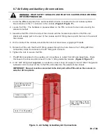
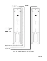
Страница 22: ...22 of 84 TO LEFT DECK ASSEMBLY Figure 11 Air Safety Auxiliary Air Connections...
Страница 26: ...26 of 84 Figure 15b Optional LED Driver Box Circuit Connections...
Страница 35: ...35 of 84 Figure 28 Filler Angle Installation...
Страница 64: ...64 of 84 20 0 ACCESSORY ASSEMBLY 20 1 Front Turnplate...
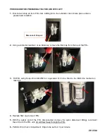
Страница 67: ...67 of 84 20 3 Airline Routing for Locking Turnplates and Rear Slip Plates...
Страница 79: ...79 of 84 22 0 POWERPACK ASSEMBLY 22 1 Powerpack Assembly EAA0441V72A...
Страница 83: ...83 of 84 APPENDIX Foundation Plan...


