


19
of
84
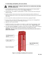
8.7 Air Safety and Auxiliary Air connections
WARNING! WEAR SAFETY GOGGLES AND PRACTICE CAUTION WHILE WORKING
WITH COMPRESSED AIR.
1. Uncoil the
Ø6mm
polytube from each baseframe that is connected to the air release cylinder.
Route this line to the ‘Y’ connector in the console. (
Figure
9
,
Figure
11
)
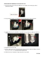
2. Locate the FRL. The hardware is preassembled on the FRL, remove the two nuts ensuring the
screws do not fall.
3. Assemble the FRL unit to the side of the console with the hardware provided on the FRL unit.
Orient with supply port to the rear of the console and 90
°
fitting lined up with the hole in the side of
the console.
4. On the inside of the console, assemble the nuts but leave loose, engaging 2 threads.
5. Rotate the FRL such that the 90
°
fitting passes through the hole. Secure the T-fitting (
Ø10 Air
connection)
inside the console to the 90
°
fitting with a wrench.
6. Tighten the nuts to secure the FRL
.
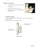
7. The
Ø10mm
polytube for the auxiliary air connections is coiled from left side baseframe. Route
this hose to the console and connect it to the T- fitting inside the console. (
Figure
9
,
Figure
11
)
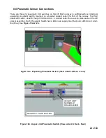
8. A 3/8” NPT fitting (
not supplied
), is needed to connect shop air supply to the Air Filter / Regulator/
Lubricator Unit. Connect air line to the FRL unit located on the outside of the console.
IMPORTANT: Shop air must be connected to the inlet port at the FRL unit on the console, in
order for lift to operate.
Attach FRL unit to the side
the console with hardware
provided
Customer to supply 3/8”
connector for airline
Secure the T-fitting to the 90
°
fitting on the FRL unit (Ø10
air connection)
Union “Y” for
Ø6
polytube
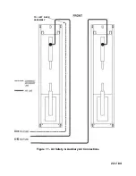
Figure 9 - Air Safety & Auxiliary Air Connections
Содержание EELR587A
Страница 7: ...7 of 84 3 0 SAFETY WARNING DECALS...
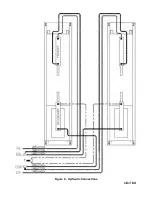
Страница 18: ...18 of 84 Figure 8 Hydraulic Connections...
Страница 22: ...22 of 84 TO LEFT DECK ASSEMBLY Figure 11 Air Safety Auxiliary Air Connections...
Страница 26: ...26 of 84 Figure 15b Optional LED Driver Box Circuit Connections...
Страница 35: ...35 of 84 Figure 28 Filler Angle Installation...
Страница 64: ...64 of 84 20 0 ACCESSORY ASSEMBLY 20 1 Front Turnplate...
Страница 67: ...67 of 84 20 3 Airline Routing for Locking Turnplates and Rear Slip Plates...
Страница 79: ...79 of 84 22 0 POWERPACK ASSEMBLY 22 1 Powerpack Assembly EAA0441V72A...
Страница 83: ...83 of 84 APPENDIX Foundation Plan...


