


36
of
84
9.1 Installation of Line Covers
1. Install line covers once console is installed and hydraulic lines are routed.
2. Position line cover “A” behind the base frames as shown.
3. Place line cover “B” close to line cover “A”, and adjust the position to make the square holes of
the line cover “B” covered by line cover “A”.
4. Position the line cover “C” close to the line cover “B”, and lay the other line cover “C” close to
the located line cover “C” as shown.
5. The number along each side of the line covers represents the quantity of fasteners required to
secure them in place. Using a Ø8 concrete drill bit, drill holes as required and install the
supplied “HEXAGONAL EXPANSION SCREW ”(1-10789A).
Note: Tapcon or equivalent concrete screws can be used as an option for future removal.
Figure 29 - Line Covers Layout
Optional:
To locate the console on left side of lift, please put the line cover “C” on the other side.
Содержание EELR587A
Страница 7: ...7 of 84 3 0 SAFETY WARNING DECALS...
Страница 18: ...18 of 84 Figure 8 Hydraulic Connections...
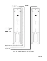
Страница 22: ...22 of 84 TO LEFT DECK ASSEMBLY Figure 11 Air Safety Auxiliary Air Connections...
Страница 26: ...26 of 84 Figure 15b Optional LED Driver Box Circuit Connections...
Страница 35: ...35 of 84 Figure 28 Filler Angle Installation...
Страница 64: ...64 of 84 20 0 ACCESSORY ASSEMBLY 20 1 Front Turnplate...
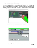
Страница 67: ...67 of 84 20 3 Airline Routing for Locking Turnplates and Rear Slip Plates...
Страница 79: ...79 of 84 22 0 POWERPACK ASSEMBLY 22 1 Powerpack Assembly EAA0441V72A...
Страница 83: ...83 of 84 APPENDIX Foundation Plan...


