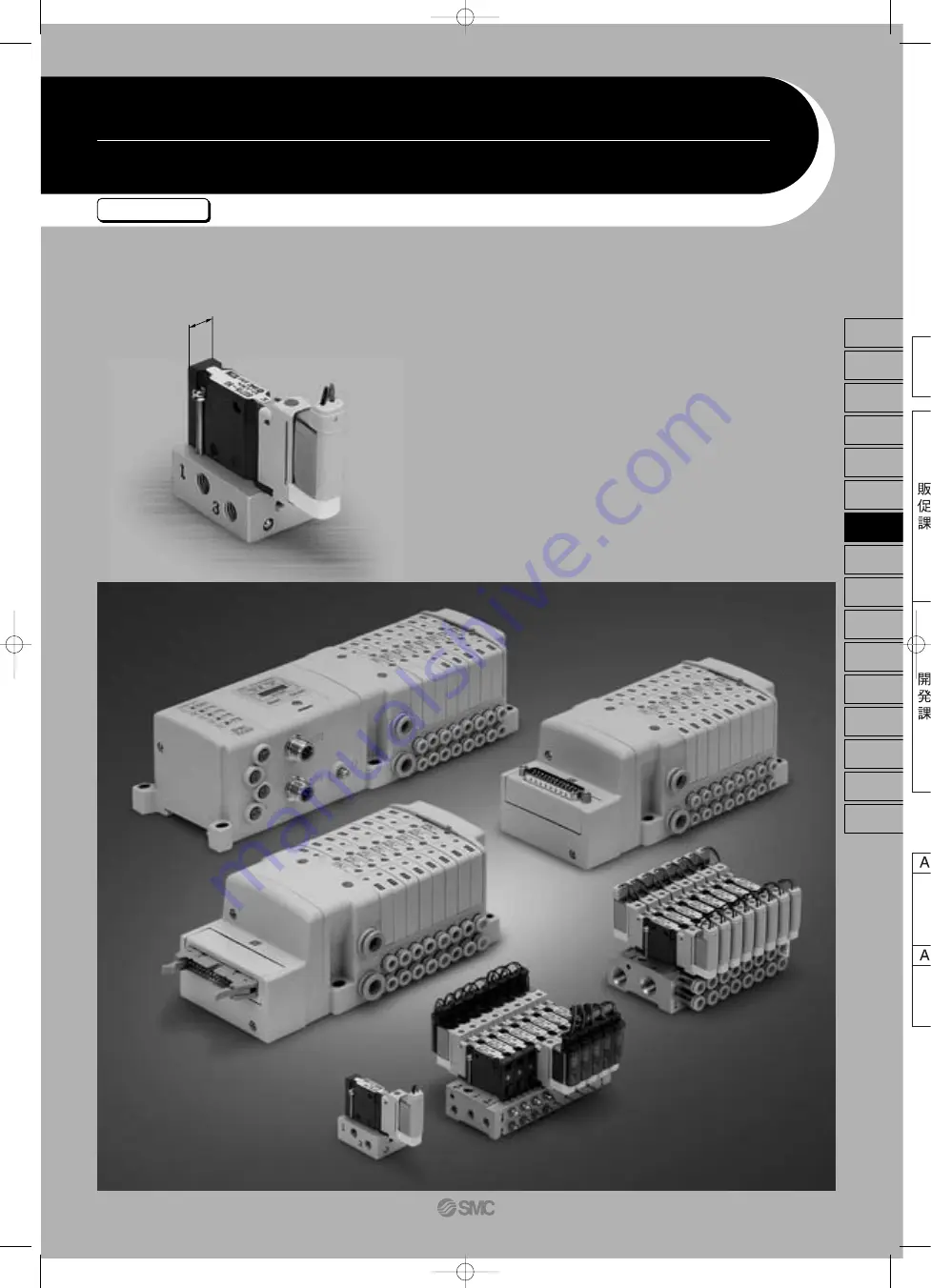
SMC Networks S0700 Скачать руководство пользователя страница 1

Series

 S0700

7 mm Width Compact Pilot Type 5 Port Solenoid Valve

Rubber Seal


7

7

Width:


7

mm

0.39

0.39

0.11

Flow Characteristics

C

[

dm

3

/(s·bar)

]: 

0.39

b: 

0.39

Cv: 

0.11

609

SJ

SY

SV

SYJ

SZ

VP4

S0700

VQ

VQ4

VQ5

VQC

VQZ

SQ

VFS

VFR

VQ7

P0609-P0680-E080904.qxd  08.9.4 11:34 AM  Page 609

Содержание S0700

Страница 1: ...t Type 5 Port Solenoid Valve Rubber Seal 7 7 Width 7mm 0 39 0 39 0 11 Flow Characteristics C dm 3 s bar 0 39 b 0 39 Cv 0 11 609 SJ SY SV SYJ SZ VP4 S0700 VQ VQ4 VQ5 VQC VQZ SQ VFS VFR VQ7 P0609 P0680...

Страница 2: ...or less 12 or less 10 or less 12 or less Single Double Dual 3 port valve C dm3 s bar 0 39 0 39 0 34 0 39 0 39 0 34 b 0 39 0 39 0 34 0 39 0 39 0 34 Cv 0 11 0 11 0 09 0 11 0 11 0 09 4 2 5 3 A B R1 R2 C...

Страница 3: ...ntrolNet CANopen EtherNet IP EX500 EX510 EX250 Gateway System Serial Transmission System Gateway System Serial Transmission System Integrated Type For I O Serial Transmission System Two 3 port valves...

Страница 4: ...silencer Direct exhaust S P 648 EXH block plate SS0700 B R P 649 Blanking plate with output SS0700 1C P 650 External pilot R P 648 P 648 SUP block plate SS0700 B P Spacer for Individual SUP EXH SS070...

Страница 5: ...06 P 650 Silencer for EXH port AN200 KM8 P 651 Perfect block Separated VQ1000 FPG P 652 Blanking plug for one touch fitting KJP 02 KQ2P 23 04 06 P 666 Silencer for manifold EXH port AN110 01 P 666 Do...

Страница 6: ...0 C Note 1 5 Hz Push type Not required 30 100 m s2 IP40 24 VDC 10 of rated voltage Class B or equivalent DC 0 35 W 15 mA Plug in type Common exhaust Note 2 24 VDC Plug lead type Individual exhaust Sta...

Страница 7: ...3 R C8 for 8 Option Direct exhaust with built in silencer Type of connection SS0750 SS0755 C C Manifold pitch 8 5 S07 5 5 M5 SS0755 V C Manifold pitch 7 5 Note 1 Maximum stations in case of mixed sin...

Страница 8: ...center 4 position dual 3 port N O N O Pressure center 4 position dual 3 port N C N O A 4 B 2 5 R1 1 P 3 R2 A 4 B 2 5 R1 1 P 3 R2 4 A 2 B 5 R1 1 P 3 R2 4 A 2 B 5 R1 1 P 3 R2 4 A 2 B 5 R1 1 P 3 R2 Seri...

Страница 9: ...ing Base Gateway System Serial Transmission System EX500 P 618 Integrated Type For I O Serial Transmission System EX250 P 620 617 SJ SY SV SYJ SZ VP4 S0700 VQ VQ4 VQ5 VQC VQZ SQ VFS VFR VQ7 P0609 P068...

Страница 10: ...refer to pages 648 to 652 For manifold exploded view refer to page 654 Symbol Kit name 1 to 8 stations Decentralized serial wiring serial transmission S kit Kit name Specification Symbol Without seria...

Страница 11: ...port inch size DIN rail clamp screw 60 12 33 6 7 5 8 5 17 2 6 5 9 6 17 5 1 P port C8 8 For A B port metric size N9 5 16 For A B port inch size 2n x C2 C3 C4 N1 N3 4 A 2 B port C2 One touch fitting for...

Страница 12: ...gs Note 5 For details refer to page 648 For manifold optional parts refer to pages 648 to 652 For manifold exploded view refer to page 654 Symbol Nil Kit name For I O serial transmission S kit Kit nam...

Страница 13: ...thread 3 R port C8 8 For A B port metric size N9 5 16 For A B port inch size DIN rail clamp screw 60 12 7 5 Power supply connector M12 male thread Ground terminal 1 P port C8 8 For A B port metric si...

Страница 14: ...622 P0609 P0680 E080904 qxd 08 9 4 11 34 AM Page 622...

Страница 15: ...Standard 25 pins Cable length 1 5 m 3 m 5 m Connector entry direc tion can be changed from the top to the side and vice versa 623 SJ SY SV SYJ SZ VP4 S0700 VQ VQ4 VQ5 VQC VQZ SQ VFS VFR VQ7 P0609 P06...

Страница 16: ...ss of valve and option types Mixed single and double wiring is available as an option For details refer to Special Wiring Specifications Option below 015 030 050 wire color AXT100 DS25 D sub connector...

Страница 17: ...pecified indicate them alphabetically Example BRS Note 2 When installing a back pressure check valve on the required station enter the part number and specify the station position in the manifold spec...

Страница 18: ...1 2 3 4 5 6 7 8 n D side U side 3 R port C8 8 For A B port metric size N9 5 16 For A B port inch size R20 Min bending inner radius 44 12 7 5 1 P port C8 8 For A B port metric size N9 5 16 For A B por...

Страница 19: ...andard 26 pins 20 pins Cable length 1 5 m 3 m 5 m Connector entry direc tion can be changed from the top to the side and vice versa 627 SJ SY SV SYJ SZ VP4 S0700 VQ VQ4 VQ5 VQC VQZ SQ VFS VFR VQ7 P060...

Страница 20: ...SOL B SOL A SOL B SOL A SOL B SOL A SOL B SOL A SOL B SOL A SOL B COM COM 1 station 2 stations 3 stations 4 stations 5 stations 6 stations 7 stations 8 stations 9 stations 10 stations 11 stations 12...

Страница 21: ...efer to pages 648 to 652 For manifold exploded view refer to page 654 Symbol Nil Kit name Cable length Kit name Specification Symbol Standard station Max number of stations for special wiring specific...

Страница 22: ...5 S0710 5 S0710 5 S0720 5 S0720 5 S0720 5 S07A0 5 S07A0 5 39 35 5 5 5 25 L4 L3 L2 47 1 4 4 L1 1 5 5 12 n 1 x 8 5 8 5 13 60 4 72 62 12 8 Mounting hole for 4 x M4 Applicable connector Flat ribbon cable...

Страница 23: ...2 20 pins PC Wiring System Compatible Flat Ribbon Cable MIL Standard 20 pins PC Wiring System compatible 631 SJ SY SV SYJ SZ VP4 S0700 VQ VQ4 VQ5 VQC VQZ SQ VFS VFR VQ7 P0609 P0680 E080904 qxd 08 9 4...

Страница 24: ...ts for a double solenoid type The total number of solenoids points must not exceed 16 1 How to order valves Indicate an option symbol K for the manifold no and be sure to specify the mounting position...

Страница 25: ...or details refer to page 648 For manifold optional parts refer to pages 648 to 652 For manifold exploded view refer to page 654 Symbol Nil Max number of solenoids Single type 1 Double Dual 3 port type...

Страница 26: ...clamp screw 33 6 17 5 9 6 6 5 17 2 8 5 7 5 12 60 1 P port C8 8 For A B port metric size N9 5 16 For A B port inch size 2n x C2 C3 C4 N1 N3 4 A 2 B port C2 One touch fitting for 2 C3 One touch fitting...

Страница 27: ...Plug in T Kit Terminal Block With Terminal Block P 636 635 SJ SY SV SYJ SZ VP4 S0700 VQ VQ4 VQ5 VQC VQZ SQ VFS VFR VQ7 P0609 P0680 E080904 qxd 08 9 4 11 34 AM Page 635...

Страница 28: ...l block cover Step 2 The diagram below shows the terminal block wiring schematic All stations are provided with double solenoid wiring Connect each wire to the power supply side according to the marki...

Страница 29: ...enter the part number and specify the station position in the manifold specification sheet Note 3 The available number of stations is larger than the number of manifold stations Note 4 Indicate the wi...

Страница 30: ...ch size 77 7 45 5 12 7 5 35 8 5 17 2 6 5 9 6 17 5 33 6 60 DIN rail clamp screw 1 P port C8 8 For A B port metric size N9 5 16 For A B port inch size 2n x C2 C3 C4 N1 N3 4 A 2 B port C2 One touch fitti...

Страница 31: ...Plug in L Kit Lead Wire Lead Wire Direct Entry Type P 640 639 SJ SY SV SYJ SZ VP4 S0700 VQ VQ4 VQ5 VQC VQZ SQ VFS VFR VQ7 P0609 P0680 E080904 qxd 08 9 4 11 34 AM Page 639...

Страница 32: ...4 1 How to order valves Indicate an option symbol K for the manifold no and be sure to specify the mounting position and number of stations of the single and double wiring by means of the manifold spe...

Страница 33: ...than the number of manifold stations Note 4 Indicate the wiring specification for mixed single and double wirings Note 5 For details refer to page 648 For manifold optional parts refer to pages 648 t...

Страница 34: ...ric size N9 5 16 For A B port inch size DIN rail clamp screw 60 33 6 17 5 9 6 6 5 17 2 8 5 7 5 12 1 P port C8 8 For A B port metric size N9 5 16 For A B port inch size 2n x C2 C3 C4 N1 N3 4 A 2 B port...

Страница 35: ...Plug in M Kit Circular Connector Circular Connector 26 Pins P 644 643 SJ SY SV SYJ SZ VP4 S0700 VQ VQ4 VQ5 VQC VQZ SQ VFS VFR VQ7 P0609 P0680 E080904 qxd 08 9 4 11 34 AM Page 643...

Страница 36: ...26 050 Cannot be used for transfer wiring Circular Connector 1 2 3 4 5 6 7 8 9 10 11 12 13 14 15 16 17 18 19 20 21 22 23 24 25 26 SOL A SOL B SOL A SOL B SOL A SOL B SOL A SOL B SOL A SOL B SOL A SOL...

Страница 37: ...ication sheet Note 3 The available number of stations is larger than the number of manifold stations Note 4 Indicate the wiring specification for mixed single and double wirings Note 5 For details ref...

Страница 38: ...14 12 14 12 14 S0710 5 S0710 5 S0710 5 S0720 5 S0720 5 S0720 5 S07A0 5 S07A0 5 39 5 5 35 60 47 1 5 25 L4 L3 L2 4 4 L1 1 5 5 12 n 1 x 8 5 8 5 13 4 72 62 12 8 Mounting hole for 4 x M4 Indicator light Ma...

Страница 39: ...647 SJ SY SV SYJ SZ VP4 S0700 VQ VQ4 VQ5 VQC VQZ SQ VFS VFR VQ7 P0609 P0680 E080904 qxd 08 9 4 11 34 AM Page 647...

Страница 40: ...S0700 Plug in Manifold Optional Parts Blanking plate SS0700 10A 1 It is used by attaching on the manifold block for being prepared for removing a valve for maintenance reasons or planning to mount a...

Страница 41: ...on label for confirmation of the block ing position from outside is attached One label of each When ordering a block plate for EXH incor porated with the manifold no a block indi cation label is attac...

Страница 42: ...d valves When the cur rent is output from two positions at the same time the current should be 0 25 A or less Mass 34 g The plug is used to block the cylinder port when using a 5 port valve as a 3 por...

Страница 43: ...ymbol and add the number of required stations after the symbol Example SS0750 08C4FD0 D09K How to Order DIN rail only DIN rail part no AXT100 DR n L Dimension L 12 5 x n 10 5 5 5 25 35 L 1 25 P 12 5 5...

Страница 44: ...or a long time Combining the double check block with a built in pilot type double check valve and a 2 position single double solenoid valve will permit this block to be used for preventing the droppin...

Страница 45: ...ote Zinc die casted Aluminum Resin Resin Resin Resin HNBR Double S0720 A Dual 3 Port S07B0 C 5 R1 4 A 1 P 2 B 3 R2 5 R1 4 A 1 P 2 B 3 R2 5 R1 4 A 1 P 2 B 3 R2 S07C0 4 A 2 B 5 R1 1 P 3 R2 N C N O S07B0...

Страница 46: ...ype Manifold Exploded View Manifold block assembly D side end plate assembly U side end plate assembly Housing assembly and SI unit S Kit EX500 EX250 F Kit P J Kit T Kit L Kit M Kit 654 P0609 P0680 E0...

Страница 47: ...t 25 pins P kit 26 pins P kit 20 pins J kit 20 pins T kit L kit Lead wire length 0 6 m L kit Lead wire length 1 5 m L kit Lead wire length 3 0 m M kit 26 pins SI unit SI unit Input block End plate ass...

Страница 48: ...ket housing and connect the black and white lead wires The connection layout is common to all kits 2A 3A 4A 13A 1B 2B 3B 4B 5B 6B 7B 8B 9B 10B 11B 12B 13B 5A 6A 7A 8A 9A 12A 11A 10A COM Red Red COM Bl...

Страница 49: ...Lead C Kit Lead Wire Individual Connector P 658 With barb fittings With one touch fittings 657 SJ SY SV SYJ SZ VP4 S0700 VQ VQ4 VQ5 VQC VQZ SQ VFS VFR VQ7 P0609 P0680 E080904 qxd 08 9 4 11 34 AM Page...

Страница 50: ...ype of actuation Note For JIS symbol refer to page 616 Symbol 1 2 A B C Specification 2 position single 2 position double 4 position dual 3 port type N C N O 4 position dual 3 port type N O N O pressu...

Страница 51: ...nector light 2n x C2 C3 C4 M5 4 A 2 B port C2 One touch fitting for 2 C3 One touch fitting for 3 2 C4 One touch fitting for 4 M5 M5 thread 14 6 5 14 20 2 x M5 x 0 8 5 R1 port 2 x M5 x 0 8 1 P port 2 x...

Страница 52: ...660 P0609 P0680 E080904 qxd 08 9 4 11 34 AM Page 660...

Страница 53: ...iring using connectors Plug Lead S Kit Serial Transmission P 662 Gateway System Serial Transmission System 661 SJ SY SV SYJ SZ VP4 S0700 VQ VQ4 VQ5 VQC VQZ SQ VFS VFR VQ7 P0609 P0680 E080904 qxd 08 9...

Страница 54: ...ch fitting for 4 Mixed size with port plug Note With one touch fitting for 1 8 With one touch fitting for 5 32 Mixed size with port plug Note Metric Inch Note Specify Mixed size with port plug in the...

Страница 55: ...8 Double solenoid dual 3 port With plug connector light SI unit EX510 S001 Cover dia 0 9 Cross section 0 38 mm2 11 8 8 5 2n x C2 C3 C4 M5 4 A 2 B port C2 One touch fitting for 2 C32 One touch fitting...

Страница 56: ...t will be installed on the top side of the manifold s SUP EXH block How to Order Valves Example S0715 R 5G How to Order Manifold Example Indicate R for an option SS0755 08C4C R External pilot External...

Страница 57: ...ch fitting assembly for 6 18 P 11 15 5 L1 L2 L3 32 2 5 5 67 1 7 4 5 U side D side Stations 1 2 3 n Residual pressure release manual override 2n x C3 C4 C6 M5 C3 One touch fitting assembly for 3 2 C4 O...

Страница 58: ...d in the EXH port L A D 38 13 AN110 01 Dimensions Applicable fitting size d 2 3 2 4 6 Model Mass g KJP 02 KQ2P 23 KQ2P 04 KQ2P 06 A 8 2 16 16 18 L 17 31 5 32 35 D 3 3 2 6 8 0 1 1 1 1 mm Series S0700 P...

Страница 59: ...t surge voltage suppressor Symbol G M MO Electrical entry Type of actuation Plug lead Note For JIS symbol refer to page 616 Symbol 1 2 A B C Specification 2 position single 2 position double 4 positio...

Страница 60: ...50 3 31 2 With plug connector light C S0715 R M 0 M5 M5 x 0 8 3 R port 21 2 11 4 M5 x 0 8 1 P port 5 2 7 7 Manual override 7 4 2 x 3 5 mounting hole 21 4 28 3 2 3 3 19 Manual override Manual override...

Страница 61: ...2 3 4 5 6 Description No Material Body Spool Piston Manual override Adapter plate Interface gasket Zinc die casted Aluminum Resin Resin Resin HNBR Note For pilot valve assembly replacement refer to S...

Страница 62: ...e length of valve with plug connector is 300 mm When ordering a lead wire length of 600 mm or longer list the part numbers for the valve without connector and the connector assembly Note For pilot val...

Страница 63: ...ively with a force of 10 N or more Plug lead type only To attach a connector hold the lever and connector unit between your fingers and insert straight onto the pins of the solenoid valve so that the...

Страница 64: ...y pressing the manual release button It is not necessary to use the manual release button when switch ing from the side to the top Remove the cover from the side of the end plate and remove the old el...

Страница 65: ...embly Please order it in 10 piece units 8 5 mm pitch 7 5 mm pitch Applicable tubing 2 Applicable tubing 3 2 Applicable tubing 4 Applicable tubing 1 8 Applicable tubing 5 32 Barb fitting 2 Barb fitting...

Страница 66: ...to the adapter plate so that the stop per plate will not protrude from the end of the adapter plate Mounting Pilot valve assembly Adapter plate assembly Stopper plate Groove Plug lead For Barb fitting...

Страница 67: ...to water or oil splash 8 Observe the proper tightening torque There is a possibility of damaging threads if tightening ex ceeds the tightening torque range 9 Adjustment Operation DIP switches and rota...

Страница 68: ...otection function Perform an inspection to check that it is working properly be cause it can cause possible injuries Warning 1 Keep the surrounding space free for maintenace When designing a system ta...

Страница 69: ...te a large surge around the reduced wiring system Take measures to prevent an electrical surge and avoid having the wires touch each other 7 Use the product type that has an integrated surge ab sorpti...

Страница 70: ...damage Caution Maintenance Adjustment and Operation Serial Wiring EX510 Precautions 1 Do not short circuit a load If a load is short circuited excessive can cause damage to the connected devices The f...

Страница 71: ...less of rated voltage 3 Pilot valve failure Foreign matter from the air source has entered the inside of the pilot valve and has caused operating failure Open coil circuit 1 Current leakage The respo...

Страница 72: ...aught in the main valve and increased the internal leakage Replace the one touch fitting assembly Part no of the one touch fitting assembly VVQ0000 50A C2 VVQ0000 50A C3 VVQ0000 50A C4 VVQ0000 50A N1...

Отзывы: