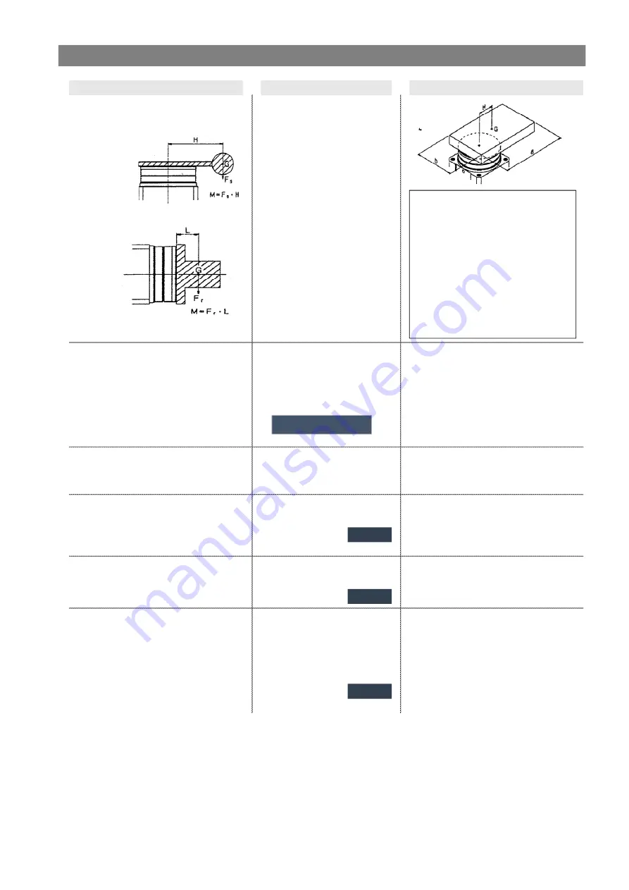
Precautions on model selection
⚠Caution
① Operating conditions
・Applicable model
Pick up operating conditions considering
・Operating pressure
mounting style.
・Mounting style
・Load type
Ts(N・m)
Tf(N・m)
Ta(N・m)
・Shape of load
Vertical mounting
・Rotation time t(s)
・Rotation angle
・Load weigth m(kg)
・Distance between axial core
H(mm)
・Mass point distance L(mm)
Horizontal mounting
②Required torque
Confirm load conditions shown below, and
Effective torque≧Ts
Inertial load
select an actuator to satisfy required torque.
Effective torque≧(3~5)・Tf
10×Ta=10×I×ω=10×0.0002×π/0.2
2
・Static load:Ts
Effective torque≧10・Ta
=0.157N・m〈Effective torque
・Resistance load:Tf
OK
・Inertial load:Ta
Note:Substitute a numerical value of
⑤ moment of inertai for I.
③Rotation time
Confirm that it is within the adjustable
0.07~0.3s/90°
0.2s/90° OK
rotation time.
④Allowable load
Thrust load:m×9.8≦Allowable load
0.15×9.8=1.47N<Allowable load OK
Confirm that radial load thrust load and
Moment:m×9.8×H≦Allowable moment
0.15×9.8×0.03=0.044N・m
moment are within allowable range.
Allowable load
Table 7
0.044N・m<Allowable moment OK
⑤Moment of inertia
Find inertial moment of load to calculate
I=m×(a
2
+b
2
)/12+m×H
2
I=0.15×(0.06
2
+0.04
2
)/12+0.15×0.03
2
energy. Find I.
Moment of inertia
Date2
=0.0002kg・m
2
⑥Kinetic energy
Confirm that kinetic energy of load is within
1/2×(I+Io)×ω
2
≦Allowable energy
1/2×(0.0002+0.000028)×(2×(π/2)/
allowable range.
ω=2θ/t(ω:Terminal angular velocity)
0.2)
2
=0.028J<Allowable energy
Note) Moment inertia of table=Io
θ:Rotationangle (rad)
OK
t:Rotation time (t)
Allowable kinetic energy
Date3
Model selection procedures
Calculation
Example
Rotary table
:
MSUA7-90S
Pressure
:
0.5MPa
Mounting style
:
Vertical
Type of load
:
Inertial load Ta
Shape of load
:
60mmX40mm
(square plate)
Rotation time t
:
0.2 sec
Rotation angle
:
90
°
Load weight m
:
0.15kg
Distance between axial core H
:
30mm
Date 1 and Graph 1
- 20 -
2020-10-13 11:15
DI987004


