- 31 -
No.JXC
※
-OMV0005-A
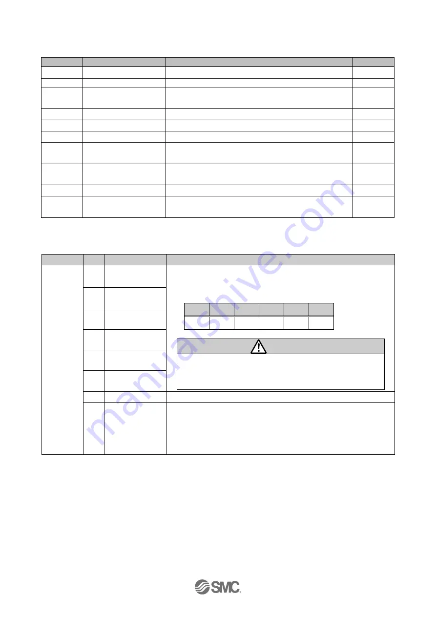
10.1.2 Process data output (from IO-Link master to JXCL1 controller)
(1) Process data output list
Byte No.
Signal name
Description
Unit
0,1
Controller control flag
Controller control signal
-
2
Run
Execution flag for numerically instructed operation
-
3
Move
Operating mode (for numerically instructed
operation)
-
4,5
Speed
Speed (for numerically instructed operation)
1mm/s
6-9
Target Posn
Position (for numerically instructed operation)
0.01mm
10,11
Accel
Acceleration (for numerically instructed operation)
1mm/s
2
12,13
Decel
Deceleration (for numerically instructed operation)
1mm/s
2
14,15
PushingF
Pushing force (for numerically instructed operation)
1%
16,17
TriggerLV
Threshold (for numerically instructed operation)
1%
18-21
InPosition
Positioning width (for numerically instructed
operation)
0.01mm
(2) Process data output details
● Byte 0: Controller control signal
Byte No.
Bit
Signal name
Description
0
0
IN0
The step data No. instruction the drive will be specified by the
combination of “IN0” to “IN5” (binary digit).
E.g.) Step data No.3 has been assigned
IN5
IN4
IN3
IN2
IN1
IN0
OFF
OFF
OFF
OFF
ON
ON
Caution
Be sure to decide the step data No. via the “IN
” signal before
turning “DRIVE” ON.
Otherwise, the actuator might operate with unexpected step
data.
1
IN1
2
IN2
3
IN3
4
IN4
5
IN5
6
-
Set always OFF(0)
7
Speed limit
When the "speed limit" flag is on, the operation will start with
limited speed range when the operation is executed.
This is valid for all operation instructions.
The flag is invalid if it is turned on during operation.
The speed limit value is different depending on the actuator type.


