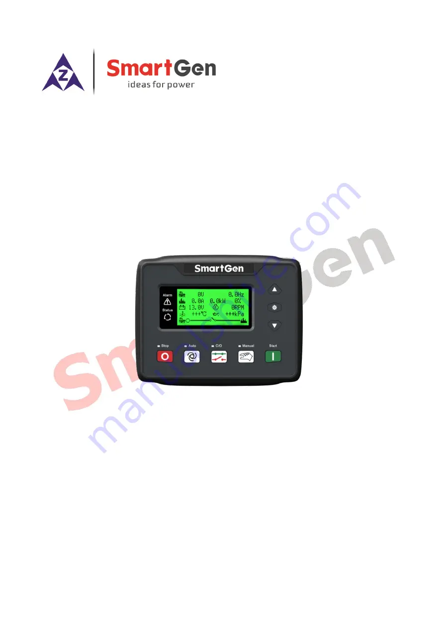
HGM4100LT
GENSET CONTROLLER
USER MANUAL
SMARTGEN (ZHENGZHOU) TECHNOLOGY CO., LTD.
Страница 1: ...HGM4100LT GENSET CONTROLLER USER MANUAL SMARTGEN ZHENGZHOU TECHNOLOGY CO LTD...
Страница 2: ...material form including photocopying or storing in any medium by electronic means or other without the written permission of the copyright holder Applications for the copyright holder s written permis...
Страница 3: ...NED CONTENTS OF CONFIGURABLE INPUT PORTS 29 7 4 SELECTION OF SENSORS 31 7 5 CONDITIONS OF CRANK DISCONNECTION SELECTION 32 8 PARAMETER SETTINGS 33 8 1 CONTROLLER PARAMETER SETTING 33 8 2 CONTROLLER IN...
Страница 4: ...HGM4100LT Genset Controller 2019 01 28 Version1 0 Page 4 of 48 13 13 MTU ADEC SAM module 45 13 14 PERKINS 45 13 15 SCANIA 45 13 16 VOLVO EDC3 46 13 17 VOLVO EDC4 46 13 18 VOLVO EMS2 46 13 19 YUCHAI 4...
Страница 5: ...t is used for single unit automation and genset auto Start Stop control by remote start signals Main characteristics LCD display with backlight 132x64 size and eight language display Chinese English S...
Страница 6: ...n be set as switch input port or programmable sensor It can be flexibly applied on different occasions Multiple temperature pressure oil level sensors can be used directly and their parameters can be...
Страница 7: ...power supply output Fuel Relay Output 5 A DC28V power supply output Programmable Relay Output 1 1 A DC28V power supply output Programmable Relay Output 2 1 A DC28V power supply output Programmable Re...
Страница 8: ...o Press this key and the controller shall be in auto mode C O The switchover key for breaker open and close press this key and the C O page and main page shall display alternately When C O page displa...
Страница 9: ...4100LT Front Panel Indication NOTE Illustration for some of indicator lights Alarm Indicators slowly flash when warning alarms fast flash when shutdown alarms light is off when none alarms Status Indi...
Страница 10: ...As soon as this delay is over start idle delay is initiated if configured 7 During the process of start idle delay under speed under frequency under voltage alarms are inhibited When this delay is ov...
Страница 11: ...auto start process 4 8 When genset high speed running goes normal press and it comes the C O interface By key Gen breaker close can be controlled and by Gen breaker open can be controlled At this tim...
Страница 12: ...m information will be displayed on LCD 4 Fail To Stop After fail to stop delay ETS delay has expired if gen set does not stop completely it will initiate a warning alarm and the corresponding alarm in...
Страница 13: ...igured in the parameter configuration is set as Warn it will initiate a warning alarm and the corresponding alarm information will be displayed on LCD 16 Oil Pressure Sensor 2 Open If the pressure sen...
Страница 14: ...splayed on LCD 24 Gen Over Frequency When controller detects the frequency is higher than the set warning value it will send warning signals and the corresponding alarm information will be displayed o...
Страница 15: ...When the controller detects the frequency value is higher than the set over frequency stop value it will send stop alarm signals and the corresponding alarm information will be displayed on LCD 6 Unde...
Страница 16: ...cuit action in parameter configuration is selected shutdown it will send stop alarm signals and the corresponding alarm information will be displayed on LCD 17 Oil Pressure Sensor Open When the sensor...
Страница 17: ...tion will be displayed on LCD 25 Maintenance Due When genset operation time exceeds the users set maintenance time and the maintenance action is set shutdown it will send stop alarm signals and the co...
Страница 18: ...ires in parallel Max 20A fuse is recommended 3 Fuel relay output 1 5mm2 B output is supplied by terminal 2 with rated 5A It is programmable relay output 5 in parameter setting 4 Start relay output 1 5...
Страница 19: ...m2 18 RS485 Common ground Impedance 120 shielding wire is recommended One end is ground connected 19 RS485 0 5mm2 20 RS485B 0 5mm2 21 Aux input 1 1 0mm2 Ground connected is active B For setting items...
Страница 20: ...me of heater plug before starter is powered up 5 Cranking Time 3 60 s 8 Power on time of starter every time 6 Crank Rest Time 3 60 s 10 The waiting time before the second power on when engine fails to...
Страница 21: ...en generator frequency has fallen below the set value but is Not equal to 0 for 10s Under Frequency is active It will initiate a shutdown alarm signal 22 Gen Over Frequency 0 75 0 Hz 57 0 When generat...
Страница 22: ...The ratio of external CT 32 Full Load Rating 5 6000 A 500 Generator s rated current it is used for over current loading calculation 33 Over Current Percentage 50 130 120 When the load current has exce...
Страница 23: ...ess of controller 59 Password Setting 0 9999 0318 For details please see NOTE 6 60 Crank Disconnection Conditions 0 6 2 Conditions for successful start of starter they are Generating Speed and Oil pre...
Страница 24: ...ed when speed sensor is not installed 76 Temp Sensor Open Circuit Action 0 2 1 0 Indication 1 Warning 2 Shutdown Indication means shall be displayed on LCD at the position of corresponding sensor 77 O...
Страница 25: ...Running delay No warning alarm is sent if the value is set 0 it is only for pressure sensor and signal of digital inputs are not included 90 Flexible Sensor Warning 80 300 C 0 400 kPa 0 100 95 Respec...
Страница 26: ...1 103 Manual Close Enable Selection 0 1 1 0 Disabled 1 Enabled When enabled switch by pressing button when disabled switch automatically 104 Raise Speed Pulse Time 0 20 0 s 0 2 Output time for speed...
Страница 27: ...vel sensor options are active 5 When parameter configuration is done via PC software there is no need to input password if default password 0318 isn t changed otherwise if default password has been ch...
Страница 28: ...is 0 it s disabled 8 Raise Speed Control Close when the generator enters into Warming Up time the pull in time is the warming up time 9 Drop Speed Control Close when the generator enters into idling...
Страница 29: ...Reserved 7 3 DEFINED CONTENTS OF CONFIGURABLE INPUT PORTS Table 9 Defined Contents of Programmable Inputs 1 5 All are ground connectedly active No Items Description 0 Not Used 1 High Temperature Shut...
Страница 30: ...e Control Mode When the input is active keys on the panel are locked except for and remote mode will be displayed on the LCD Remote control module pattern can be switched by the key on the panel 17 Ch...
Страница 31: ...12 Digital Open Users defined resistance type range is 0 999 9 default is SGX sensor 2 Pressure Sensor 0 Not used 1 User Configured Resistor type Curve 2 VDO 10Bar 3 SGH 4 SGD 5 CURTIS 6 DATCON 10Bar...
Страница 32: ...Speed stands for the real rotation speed detected by the speed sensor Speed sensor is the magnetic equipment which is installed in the starter for detecting flywheel teeth 3 When speed is chosen make...
Страница 33: ...simultaneously c Over speed set value must be higher than under speed set value otherwise over speed and under speed conditions may occur simultaneously d Please set the generator frequency value as...
Страница 34: ...This item can set display languages Chinese English Spanish Russian Turkish French Portuguese and Polish 8 4 EVENT LOG Through this item event log information can be checked including start stop infor...
Страница 35: ...ers can choose defined sensor and input defined sensor curve At the time of inputting the sensor curve X value resistor must be inputted from small to large otherwise any mistake may occur If there is...
Страница 36: ...under manual mode press start button and the genset will start After the set cranking times the controller will send Start Failure signal and then press stop to reset the controller Recover the action...
Страница 37: ...HGM4100LT GENSET CONTROLLER USER MANUAL HGM4100LT Genset Controller 2019 01 28 Version1 0 Page 37 of 48 11 TYPICAL APPLICATION Fig 4 HGM4100LT Typical Application Fig 5 HGM4100LT Typical Application...
Страница 38: ...NG CLIPS 1 The controller is panel built in design and it is fixed by clips for installation 2 Withdraw the fixing clip screws anticlockwise until they reach proper position 3 Pull the fixing clips ba...
Страница 39: ...during the full speed range AC12V is recommended at rated speed When speed sensor is installed let the sensor spun to contacting flywheel first then port out 1 3 lap and lock the nuts of sensor at la...
Страница 40: ...1939 shield CAN communication shielding line connected to ECU terminal only CAN H SAE J1939 signal Using impedance 120 connecting line CAN L SAE J1939 return Using impedance 120 connecting line Engine...
Страница 41: ...munication shielding line connected to ECU terminal only CAN H A Using impedance 120 connecting line CAN L B Using impedance 120 connecting line Engine type Cummins ISB 13 4CUMMINS QSX15 CM570 It is s...
Страница 42: ...ly Table 22 D SUB Connector 06 Terminals of controller D SUB connector 06 Remark RS485 GND 20 CAN communication shielding line connected to ECU terminal only RS485 21 Using impedance 120 connecting li...
Страница 43: ...gine type Common J1939 13 8DETROIT DIESEL DDEC III IV Table 25 Engine CAN Connector Terminals of controller CAN port of engine Remark Programmable output1 Expand 30A relay supplying battery voltage fo...
Страница 44: ...output 1 as Fuel Relay Output Start relay output BE9 CAN GND E CAN communication shielding line connected to one terminal only CAN H G Using impedance 120 connecting line CAN L F Using impedance 120...
Страница 45: ...39 13 14 PERKINS It is suitable for ADEM3 ADEM4 engine control mode Engine type is 2306 2506 1106 and 2806 Table 33 Connector Terminals of controller Connector Remark Programmable output1 1 10 15 33 3...
Страница 46: ...impedance 120 connecting line Engine type Volvo NOTE When this engine type is selected preheating time should be set at least 3 seconds 13 17 VOLVO EDC4 It is suitable for engine types TD520 TAD520 op...
Страница 47: ...40 Set configurable output 1 as Fuel Relay Output Connected to engine ignition lock Start relay output Connected to starter coil directly CAN_SCR CAN communication shielding line CAN H 1 35 Using imp...
Страница 48: ...ctions Shutdown Alarm in running Check related switch and its connections according to the information on LCD Check programmable inputs Crank failure Check fuel oil circuit and its connections Check s...