SMARTEYE
Netx Ethernet IP Control Unit User Manual
Page 42
Filename: netx IP Platform User Manual R0 .doc
…
In Control
A
M
12.1 Ethernet IP Control Port Operation
The Smarteye Netx Control Unit communicates over the Ethernet IP network to the control
system PLC. The Netx Control Unit is setup as a server and listens for in-coming connection
request on port 44818. After a connection has been established, the Netx Control Unit will begin
sending I/O data to the PLC using UDP messages on port 2222.
Most of the configuration settings required to get the Netx Control Unit communicating over
Ethernet IP with the PLC is done on the PLC side. The Netx Control Unit only needs its’
network parameters set to match the parameters of the network it will reside on. The Netx’s IP
address, network mask, and gateway (if required) will need to be configured before it can
communicate with the PLC.
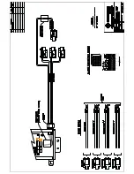
For the Ethernet IP port interconnection diagram (cable pin out configuration), refer to the
Ethernet connection Wiring Details in ‘Appendix’.
12.2 Auxiliary Port Operation
The auxiliary port is used to display reader activity and for system inquiries. The auxiliary port
is factory configured to communicate in the RS232 standard. The baud rate and parity used for
the auxiliary port is user selectable. The factory default settings for the auxiliary port are
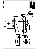
RS232, 57600 baud, 8 bits, 1 stop bit and no parity. For the auxiliary port interconnection
diagram, refer to the Auxiliary Port Wiring Details in the ‘Appendix’. If the Bluetooth interface
option is purchased, the auxiliary port is configured for Bluetooth data mode.
13.0 Diagnostic
Enable
A diagnostic message contains five numbers which indicate whether the reader needs
maintenance. An ideal diagnostic reading is:
A
B
C
X
Y
+5
+5
+5
0
0
Diagnostic numbers are acceptable if they are within ±5 of the perfect reading shown above. If
an acceptable reading is unobtainable, check the Smarteye Reader User Manual for alignment
information.
The Smarteye Netx Control Unit calculates a diagnostic message each time a label passes by one
of its readers. The diagnostic message is transmitted to the host only after the control unit
receives an L (lock command) or diagnostic is configured to ON. Once the reader is locked in
diagnostic mode, then each time a label passes a reader, a diagnostic message is transmitted to
the host. The diagnostic message comes in addition to any messages (label message, error
message, etc.), which would appear if the reader were not in diagnostic mode.
The U (unlock) command disables diagnostic mode for the reader selected. Upon power-up,
diagnostic mode is disabled for the reader. This is only true if diagnostic is configured to OFF.
Содержание Multi-netx
Страница 2: ......
Страница 51: ......
Страница 52: ......
Страница 53: ......
Страница 54: ......
Страница 55: ......
Страница 56: ......
Страница 57: ......
Страница 59: ......
Страница 60: ......
Страница 61: ......
Страница 62: ......
Страница 63: ......
Страница 64: ......
Страница 65: ......
Страница 67: ......
Страница 68: ......
Страница 69: ......
Страница 70: ......
Страница 71: ......
Страница 72: ......
Страница 73: ......
Страница 74: ......
Страница 75: ......
Страница 76: ...www smarteyecorporation com ...


