background image

http://www.SkyhawkRC.com

http://www.SkyhawkRC.com

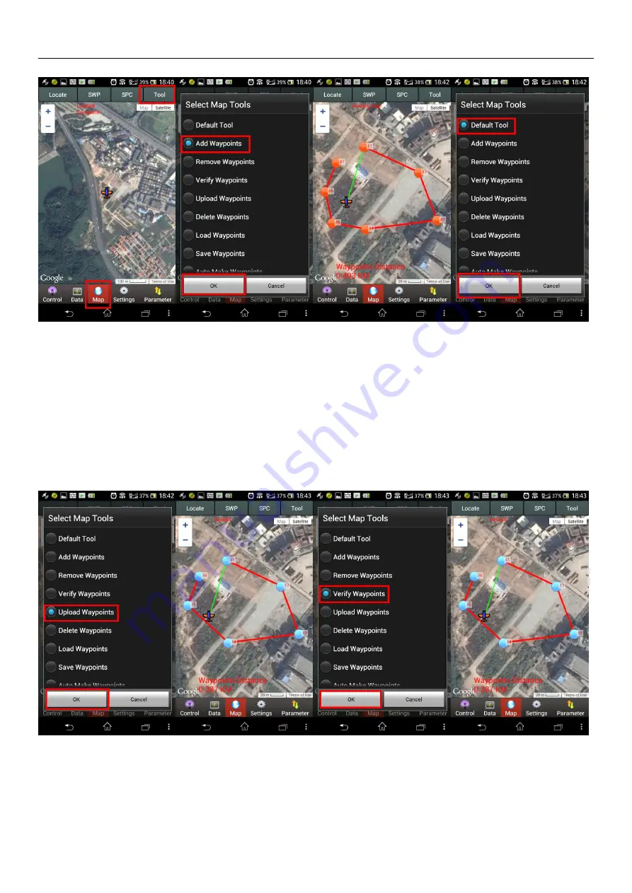
4). click “Tool” and “Default Tool” button.

Step 2: upload and verify waypoints
1). click “Tool”, “Upload Waypoints” and “OK” buttons.
2). check if all waypoints change from orange to blue and confirm if they are uploaded successfully(it indicates
that all waypoints are uploaded successfully while changing to blue color, if not, please re-upload waypoints until
all of them change to blue color).
3). click “Tool”, “Verify Waypoints” and “OK” buttons.
4). check if all waypoints are blue color and confirm if they are verified successfully(it indicates that all waypoints
are verified successfully while they are all blue color, if not, please re-upload and re-verify waypoints until all of
them change to blue color).

5). Switch remote control CH5 to “2” and CH6 to “1” position to start auto navigation
.
6). Click “SPC” and “Enable Skyway” and “OK” buttons, the aircraft will fly to the first pointed waypoint and
hovering, click “SPC”, change number “1” to “2” on the first line, aircraft will fly according to the setting

Содержание F900

Страница 1: ...http www SkyhawkRC com http www SkyhawkRC com SkyhawkRC F900 user manual V1 0 2014 07 28 ...

Страница 2: ... operation please operate it in a special site 4 The product equips with 6S Li Po battery 5 Aircraft does not equip with waterproof dustproof ability please do not operate it under bad weather or the temperature below 5 degrees 6 Aircraft belongs to precision mechanical and electrical integration product please do not make modification or disassembly otherwise it will not work normally 7 Please ch...

Страница 3: ... Remote control android mobile GCS PC GCS 5 Android mobile PC GCS parameters adjustment 6 Common receiver S BUS receiver Accessories Details Fuselage 1 PC 3K carbon fiber Titanium alloy YS X4 V2 standard Landing Gear Center Frame 1PC 3K carbon fiber Titanium alloy Landing Gear Carbon Tube 1 UNIT Accessories Bag 1 BAG Quick release key Propeller clip screws Screw Bag 1 BAG ...

Страница 4: ...ge transmission far away from receiver to avoid signal blocking or interfered and lose control 3 Please install the propellers according to the numbers between propellers and arms 4 Please do not tear installed screws down to avoid fuselage loose or damage 5 Please do not change installation place and direction of fuselage it will affect aircraft s normal working 6 To test electric retractable lan...

Страница 5: ...ding gear center board and put it on ground to keep two bottom pipes parallel and twist center board M3x8mm screws 3 Please check the landing gear manually in normal it can be retractable by hands smoothly Fuselage Installation 1 Remove packing materials put the center board up unfold the arms one by one the arms will be locked automatically while in right location Please pay attention to their mo...

Страница 6: ...s the front 2 Check rotating direction of propellers from the upper of fuselage M1 M3 M5 and M7 rotate in anticlockwise direction and M2 M4 M6 and M8 rotate in clockwise direction Power Distribution Unit PDU F900 fuselage integrates XT60 power distribution port can output two way power its voltage is equal to battery voltage Bottom two XT60 ports are for aircraft F900 ...

Страница 7: ...o use two batteries connected together the voltage of them must be same Gimbal Mount Size Technical Parameters Fuselage Diagonal Motor Wheelbase 920 mm Arm Length 422 mm Center Board Diameter 230 mm Max Spread Size 1260 x 1260 x 535 mm Fuselage Weight motors ESC propellers and flight control included 2720 g ...

Страница 8: ... weight 5 05Kg Working Temperature 5 40 Wind Resistance 5 4m s 6 5Kg take off weight Remote Control and LED Indicator Unlock and start motors For safety flight control locks throttle signal of motors motors will not start until unlock it In regards to left hand throttle Japanese user mode 1 and US users mode 2 layout need to operate outside 八 type to unlock throttle for right hand throttle Chinese...

Страница 9: ...ority User can switch to manual control mode under any other modes Landing Gear up down F900 aircraft has electric retractable gear and realize gear up down by channel 9 on remote control while power cut down user also can put the gear up down by hand while power cut No matter what position of channel 9 switch located the gear is in down state while power is on Working State CH9 Gear Down 2 Gear U...

Страница 10: ... it indicates barometer failed please restart flight control system About magnetic compass calibration To make magnetic compass calibration if attitude error is within 5 degrees blue LED is still on it indicates that user can make calibration if attitude error is out of 5 degrees blue LED is off it indicates user needs to make calibration again After completion while flight control will save data ...

Страница 11: ...ll CCS software on android mobile or tablet we will send GCS software to user after purchase done 2 Check remote control functions and android ground station data 1 Turn on remote control CH5 and CH6 switch to 0 position CH9 switches to 2 position cut down ESC power and connect flight control power open Android mobile or tablet WIFI search aircraft name M900 XXX password 54321 start GCS software s...

Страница 12: ... needs to push throttle joystick to at least half position before taking off There is no limit under manual mode 3 Execute the operation if there is no operation of pushing throttle joystick in 5 seconds the motors will stop running and be locked automatically User needs to execute the operation one more before taking off 4 Under manual mode if throttle joystick is not in bottom position motors wi...

Страница 13: ... switch to manual mode and pull throttle to bottom Step 2 click Magnetic Compass button in Settings interface Step 3 click Horizontal Alignment and OK button if user does not want to continue can click cancel Step 4 keep aircraft horizontal hold by hands make sure the blue LED is still on and rotate aircraft 5 6 circles keep blue LED on while rotation if the blue LED is off please stop and adjust ...

Страница 14: ...ircle and 1 red circle the calibration is completed excellent qualified unqualified As photos above if red and blue circles are almost in coincident it indicates calibration is successful If not please execute the operation again Note if the flight control components are installed well and no disassembly it is unnecessary to make calibration again Auto Navigation Step 1 Air line Setting 1 click Ma...

Страница 15: ...nge to blue color 3 click Tool Verify Waypoints and OK buttons 4 check if all waypoints are blue color and confirm if they are verified successfully it indicates that all waypoints are verified successfully while they are all blue color if not please re upload and re verify waypoints until all of them change to blue color 5 Switch remote control CH5 to 2 and CH6 to 1 position to start auto navigat...

Страница 16: ...0 auto hovering mode Note If not upload waypoints correctly switch to auto navigation aircraft will fly away If you have any questions about our products or service please feel free contact us by following Homepage http www SkyhawkRC com Mail SkyhawkRC gmail com Skype SkyhawkRC1 Follow us https twitter com SkyhawkRC https www facebook com skyhawkRC https plus google com SkyhawkrcOctocopter https w...

Отзывы: