22
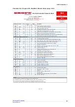
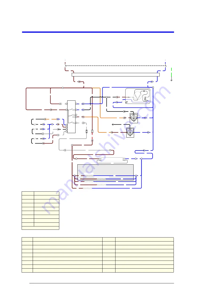
Wiring
Service Manual
SKOPE BackBar X
3
Wiring
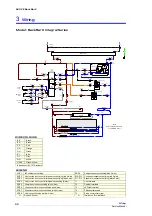
Model: BackBar X Integral Series
OG
P7-4
BK
BN
P8-1 S8-1
P7-1 S7-1
S7-2 P7-2
S5-1 P5-1
P2-1 S2-1
P3-1 S3-1
P3-2 S3-2
P3-4 S3-4
6
7
4
5
2
Fan
3
1
Lights
8
9
10
11
Carel
Smart
Controller
Comp.
T1-4
& 5
BN
BN
BU
BU
BN
BK
OG
WH
Compressor
R
S
C
L
N
Start
Compressor
Overload
Relay
T1-6
BK
S5-2 P5-2
BN
BU
BN
BU
S6-2 P6-2
P6-1 S6-1
Condenser Fan
Evaporator Fan
BU
BU
BU
BN
WH
S8-2 P8-2
BU
S4-1 P4-1
S4-2 P4-2
S4-4 P4-4
S4-3 P4-3
S9-1 P9-1
OG
BK
BK
BK
BK
S9-2 P9-2
S10-1 P10-1
S10-2 P10-2
S11-1 P11-1
S11-2 P11-2
Cabinet
Probe
Evaporator
Probe
Isolation
Switch
BN
L
BU
N
BN
BU
S1-L P1-L
P1-N S1-N
BN
BU
T1-1,
2 & 3
GNYE
E
EMC Filter
BU
BN
S2-2 P2-2
S2-4 P2-4
BU
BU
BN
BU
Fuse
Fuse
BK
BK
Condenser
Probe
Door Frame Element
T3-2
T2-3
T2-2
T3-1
LED tube
BN
BN
WH
BU
T2-1
BU
BN
BU
T4-P
BN
BN
BU
BN
BU
BN
BU
BN
BU
T4-N
BU
Pillar Element
Pillar Element
Door Frame Element
Perimeter Element
T5-1
BU
WH
RD
S8-4 P8-4
WH
BN
WH
S6-4 P6-4
BK
BK
BN
Note:
Items in shaded box are
for multiple doors .
BU
BU
BU
BN
WH
WH
BK
BU
LEGEND
S1/P1
IEC cabinet socket/plug
S9/P9
Cabinet sensor socket/plug (blue 2-way)
S2/P2
Unit junction box to controller power socket/plug (red 4-way)
S10/P10
Condenser sensor socket/plug (red 2-way)
S3/P3
Unit junction box to controller power socket/plug (blue 4-way)
S11/P11
Evaporator sensor socket/plug (black 2-way)
S4/P4
Unit junction box to controller signal socket/plug (6-way)
T1
Unit terminals
S5/P5
Compressor unit socket/plug (blue 4-way)
T2
Cabinet terminals
S6/P6
Condenser motor unit socket/plug (red 4-way)
T3
LED light terminal
S7/P7
Evaporator motor unit socket/plug (white 4-way)
T4
Pillar/door terminals
S8/P8
Light unit socket/plug (yellow 4-way)
T5
Probe common terminal
<<
Plug and Socket
O
Terminal on Terminal Block
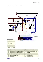
WIRE COLOURS
BK
Black
BN
Brown
RD
Red
OG
Orange
GN
Green
BU
Blue
GY
Grey
WH
White
GNYE
Green-Yellow
Based upon IEC 757 Standard


