14
15
A 5-cm air gap is located between
the sauna stove and the surrounding
wire mesh, through which air is direct
-
ed upwards when heating the stove.
The air gap is covered with perforated
cover plates from top to bottom. The
openings in the cover plates are se-
lected so as to impede free air exit. As
a result, air is partly directed through
the openings located along the sides
and edges of the stove reaching the
stones located around the fireplace
between the top of the fire pocket
and the chimney. Air passes through
the openings between the stones,
providing additional heating. With
such air-interchange system, air in the
room is heated more intensely, which
allows to heat the steam room to the
desired temperature within a short pe
-
riod of time. The user can seamlessly
replace the metal door with the glass
one on all models of the sauna stoves:
to do that, it is necessary to remove
the metal plate and replace it with
the glass one (or vice versa). When
installing glass, it must be securely fas
-
tened.
For the models shown in Drawing 4, 6,
9 and 10, decor mouldings are avail
-
able as additional devices to cover
the wall opening around the door up
to 35 mm on top and on both sides.
Decor mouldings are made either in
black (ILU-ILU-230 and 330) or of stain
-
less steel (ILU-230 RV and 330 ILU-RV).
Note: if the temperature in the steam
room drops below 0 ˚C, water must be
released from the system through the
nipple.
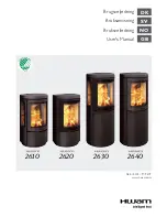
1. Popielnik/ Ash Pan
2. Kratka paleniska / Combustion
Grate
3. Komora spalania / Fire Pocket
4. Szczelina powietrzna / Air Gap
5. Baza przewodu dymowego /
Smoke Flue Base
6. Przewód dymowy /Smoke Flue
7. Otwór wyczystkowy /Cleanout
Hole
8. Koniec przewodu dymowego /
Smoke Flue End
9. Otwory przewodu dymowego /
Smoke Flue Openings
Rysunek 11. Przekrój poprzeczny pieca do
sauny /
Drawing 11. Cross Section of the Sauna
Stove
dy zbiornik wodny jest pusty. Podgrze
-
wacz wody może być używany do
ogrzewania wody w zarówno otwar
-
tym jak i zamkniętym obiegu, którego
ciśnienie robocze nie przekracza 4 kg/
cm².
znajduje się Między piecem a otacza
-
jącą go siatką drucianą znajduje się
szczelina wielkości 5 cm, przez którą
podczas nagrzewania się pieca prze
-
chodzi powietrze, by skierować się ku
górze. Szczelina pokryta jest na całej
wysokości perforowanymi płytkami.
Otwory w płytkach są dobrane tak,
aby utrudnić swobodne ujście powie
-
trza. W rezultacie, powietrze jest czę
-
ściowo kierowane przez otwory zloka
-
lizowane wzdłuż boków oraz krawędzi
pieca, dosięgając kamieni, które znaj
-
dują się w całym palenisku pomiędzy
górną częścią komory spalania a ko
-
minem. Powietrze przechodzi przez
otwory pomiędzy kamieniami, zapew
-
niając dodatkowe ogrzewanie. Sto
-
sując taki system wymiany powietrza,
powietrze w pokoju jest podgrzewane
bardziej intensywnie, co pozwala na
nagrzanie pomieszczenia parowego
do pożądanej temperatury w krót
-
kim czasie. We wszystkich modelach
pieców do sauny użytkownik może
bez problemu wymienić metalowe
drzwiczki na szklane: aby to zrobić
należy wyjąć metalową płytę i zasta
-
pić ją szybą (lub odwrotnie). Prosimy
upewnić się, że szyba jest bezpiecznie
przymocowana.