


Use and Maintenance Manual
–
002.108A of _27/09/2021
Square Baler
–
M 60 Mini/S
–
M 60 Mini
–
M 60 Super
59
ENGLIS
H
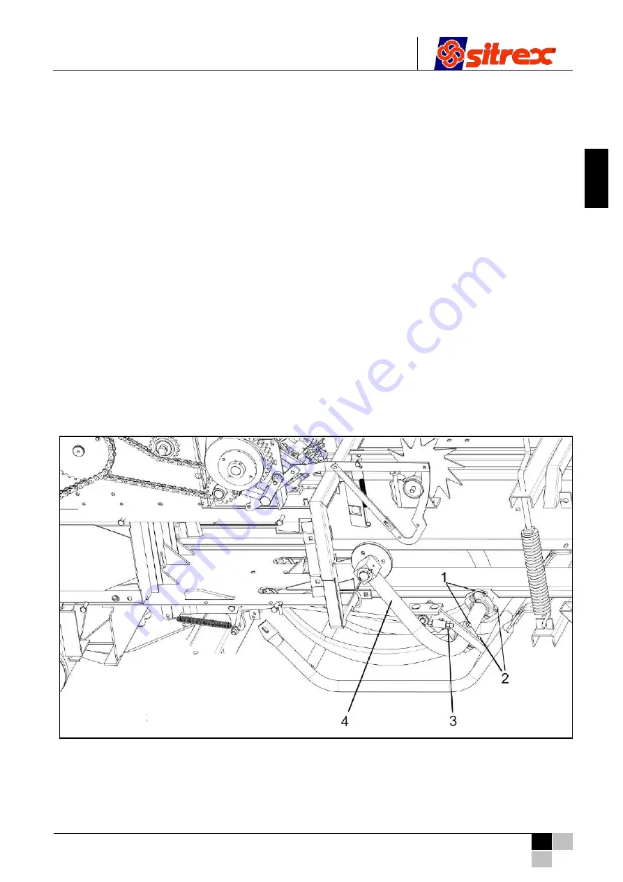
7.4.4 Needles adjustment
The needles are adjusted using screws 1 and 2 as shown in Fig. 7.14.
1) To reduce the distance between the needle tips and the holder disc when they bring the thread to
the knotter, loosen screw 2 by a fraction of a turn and tighten screw 1 by the same amount.
To increase the aforementioned distance, make the adjustment in the opposite manner.
2) To move the needles sideways, bend them as much as necessary.
To obtain an accurate regulation, refer to the measurements below:
Adjustment of the crosswise position of the needles.
The distance between the side of the needle and the knotter frame must be 0.5 to 1 mm (ref. C,
Fig. 7.13), i.e. the needle must almost touch the knotter frame (Fig. 7.13).
This adjustment is usually made with the needle arm in neutral, bending the needle itself.
3) Needle height adjustment.
When the needle is at the upper end of the stroke, the distance between the lower side of the
needle and the bottom of the notch of the holder disc must be 18
–
22 mm (ref. D, Fig. 7.13).
This adjustment is usually made with the needle arm in neutral, loosening or tightening screws 1
and 2 (Fig. 7.14).
4) Needle advancement adjustment.
When the needles reach the upper end of the stroke (ref. E, Fig. 7.13), the distance between the
holder disc and the center of the needle roller must be between a minimum of 80 mm and a
maximum of 85 mm.
To adjust this height, use the adjustable fork of the needle holder arm (ref. 6, Fig. 7.13).
Fig. 7.14


