background image

Ż

GOTO

       Position Navigation

PLOT

Ź

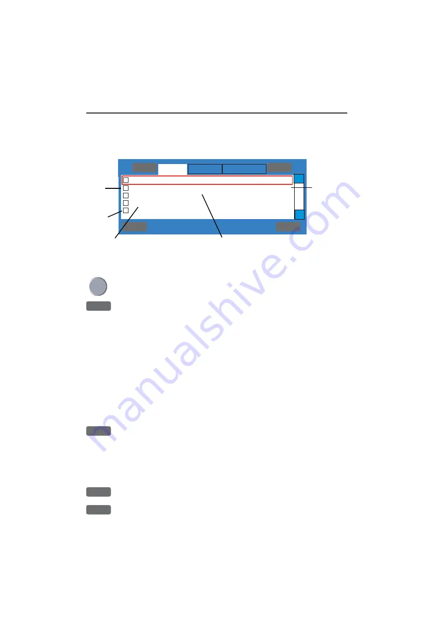
+   1: Simrad CX34-1        ,Sn:3D69AB
+   2: Simrad EQ44-2        ,Sn:0070B0
+   3: Airmar EQS           ,Sn:000000
+   4: Simrad RC35          ,Sn:000035
-

: NMEA-PORT

MENU

 Exit                                           Accept 

ENT

Ʃ

Ʃ

Nodes

Addi-
tional 
data

No addi-
tional 
data

Internal 
serial 
number

Automatically assigned 
network address

Product model numbers (top line is own unit); -1, -2, -3 
etc. indicates multi sources. NMEA-PORT indicates 
incoming data via the NMEA port.

Chapter 9-14 

 Setup menu

Searching interface channels for valid sources and data. Please wait 
till the first page appears on the screen which will show the nodes 
(products) operating on the SimNet bus. See below example:

Move the cursor up/down to select one of the listed products

+

Press the 

[+]

 key to access additional data

Example:

• CX34     NAVSTATION
• SimNet number=3D69AB, Address:  1
• Device: class = 60, function = 170
• Instance: system =  0, device =  1
• SimNet:Compatible =YES,Ver= 1.000 E
• Ver.: NMEA2000 = 1.004, SW =  03.00
• Product code =007F,Unique no =138384

The name 

NAVSTATION

 can be user defined - see the Identification 

interface (last tab).

-

Press the 

[-]

 key to hide additional data

General information: 

Go to the next interface by pressing [PLOT] 

and step back to the previous interface by pressing [GOTO].
Use the cursor key to move around in the display and toggle between 
available settings and sentences with the +/- keys. 

ENT

Confirm editing, or...

MENU

exit function without making any changes

Содержание DX45

Страница 1: ...energy Continuous exposure to RF energy may cause harmful effects to the human body It also causes Cardiac Pacemaker to malfunction A person who uses a Cardiac Pacemaker should under no circumstances be exposed to RF radiation Most countries accept that RF power density levels below 100 W m2 cause no significant RF hazard Please read the Safety Notices on the next page ...

Страница 2: ...s or omissions in the publication although every care has been taken to make it as complete and accurate as possible This manual provides information for installation safety notices and mainte nance safety of the radar scanner DX45 60 The installation will require connection to a compatible display unit CX34 44 54 A typical radar system is illustrated below Radar scanner Display unit GPS antenna C...

Страница 3: ...ifications Maintenance safety Beware of residual high voltages High voltages may remain in the capacitors several minutes after you have turned the power switch off and disconnected the cable between the radar scanner and display unit Wait for at least five minutes or discharge them to ground before starting your inspection Main power supply must be disconnected To prevent electrical injury due to ...

Страница 4: ...dar scanner requires servicing or repair call your authorized SIMRAD dealer but first check Troubleshooting on next page Troubleshooting Symptom Possible cause Suggested solution Scanner is not respond ing Cable is damaged or not firmly attached to display unit Check that the cable connecting the scanner to the display unit is firmly attached turn the plug as far as it will go into the receptacle ...

Страница 5: ...ation failure alarm check connection to scanner Communication time out failure alarm no communication between display and scanner Guard Zone alarm see GZ under section 3 2 5 Heading missing alarm check connection to compass Position missing alarm see Position update under section 6 3 Rotation lock alarm check if scanner is rotating Trigger fail alarm check connection to scanner refer to display un...

Страница 6: ...Page VI ...

Страница 7: ...function 2 Initial start up of radar function 2 1 2 1 The scanner needs to warm up 2 1 2 2 Radar operation from display unit 2 1 2 2 1 Go to Standby 2 2 2 2 2 Resume radar transmission from Standby 2 2 2 2 3 Resume radar transmission from Standby 2 2 Chapter 3 Radar operation 3 Radar operation 3 1 3 1 Radar picture 3 1 3 1 1 Orientation 3 1 3 1 2 Effects of ship s movement 3 2 3 1 3 Environmental ...

Страница 8: ... Page no Chapter 4 Specifications 4 Specifications 4 1 4 1 DX45 Radome scanner 4 1 4 2 DX60 Radome scanner 4 3 Index end of manual EU Declaration of Conformity end of manual International warranty end of manual List of Simrad distributors end of manual ...

Страница 9: ...ted by various factors Therefore consider the fol lowing suggestions when you determine the place to install the scanner A Install scanner away from smoke stack and mast If the scanner is installed at the same height as the smoke stack or mast radar waves may be blocked crating shadow zones or generating false echoes Therefore do not install the scanner at such a position B Install scanner forward...

Страница 10: ...to obstacles using the following equation Ls 0 4R D 2 m when R 15 m Ls 0 025R D 2 m when R 15 m where Ls distance to be shifted from keel line D diameter of obstacle on keel line R distance from scanner to obstacle Scanner unit Obstacle Keel line Obtaining sufficient dip angle Raise the scanner position so that there is a sufficient dip angle available between the line of sight from the scanner to...

Страница 11: ... located at the bottom of the scanner unit during installation When the radar mast or mounting bracket has a curvature of more than 2 mm repair it or use spacers Mount base Do not use an edge that might trap water Which size bolts to use for mounting of scanner unit Thickness of mount base Bolt requirement Material Remarks 1 4 mm 0 04 0 16 in M10 15 1 5 mm pitch Steel 4 9 mm 0 16 0 35 in M10 20 1 ...

Страница 12: ...tion 1 4 Radar scanners DX45 60 DX45 Radome scanner 46 5 cm radome 4 kW Range up to 28 nm Rotation speed 20 50 rpm Beamwidth Horizontal 5 6 Vertical 30 The four bolts included will suffice for mount base thickness of 9 to 14 mm 0 35 to 0 55 in If the mount base is thicker or thinner than this prepare bolts as listed on page 1 3 Use silicone to secure the bolts ...

Страница 13: ...rt of radome scanner DX60 If the DX60 is to be mounted on a flat surface the four pads included for support have to be placed according to this illustration To fit the pads peel off the paper and place it with the adhesive part on to the radome bottom The four bolts included will suffice for mount base thickness of 9 to 14 mm 0 35 to 0 55 in If the mount base is thicker or thinner than this prepar...

Страница 14: ...ly cable Run the radar cable along the ship s hull or wall surface and fasten it at intervals of about 40 cm The scanner side of the radar cable has to be fitted inside the radome scanner see Interconnecting cable next page The power cable delivered with the display unit must be fitted with two fuses before connecting the radar scanner see fuse types in specifications After fitting the Interconnec...

Страница 15: ...inlet place the rubber ring around the cable and clamp the cable to the scanner unit with screws via the fixing plate See Fitting interconnecting cable for DX45 and DX60 further on in this sec tion Connect 8 pin connector to X5 and 11 pin connector to X6 of PCB Replace the aluminum cover Attach a cable shield onto a ditch with the alu minum cover Be careful that the cable does not get caught betwe...

Страница 16: ...or on PCB X11 X12 Radome bottom Fixing plate Rubber ring Interconnection cable X6 Connect here Radome bottom PCB X5 Connect here See wire colors and pin numbers on next page Installation 1 8 Radar scanners DX45 60 Fitting interconnection cable DX45 and DX60 ...

Страница 17: ...Radar scanners DX45 60 Installation 1 9 Wire colors and pin numbers for the DX45 and DX60 Radar scanner ...

Страница 18: ...re Crimp terminal Installation 1 10 Radar scanners DX45 60 1 2 4 Grounding wire Connect grounding wire from one of the bolts used for mounting the scanner unit to ship s hull The crimp terminal and grounding wire are not included with the radar equipment Radome ...

Страница 19: ...take to properly warm up the scanner This way you will contribute to the lifetime of the magnetron in the radar scanner Note Normal start up at regular usage will take approx two minutes for the scanner to warm up and be ready for transmission 2 2 Radar operation from display unit To activate the radar transmission RADAR Shortcut to radar display ENT Call up the Radar quick menu RADAR Turn Power o...

Страница 20: ...tion to Standby mode ENT Call up the Radar quick menu GOTO Enter Standby mode 2 2 2 Resume radar transmission from Standby To resume the radar transmission ENT Call up the Radar quick menu GOTO Start transmission 2 2 3 Resume radar transmission from Standby To shut down the radar function ENT Call up the Radar quick menu RADAR Turn Power off ...

Страница 21: ... s dead ahead bearing is indicated by the heading line at the 0 relative bearing Coastline contours and landmass are generally depicted in solid filled yellow purple multi colored DAY settings or green NIGHT settings echo areas choose colors in Pallette setup section 9 7 Other surface vessels and channel buoys are displayed as smaller single blips or echoes The radar picture or map can be viewed i...

Страница 22: ...p s heading in relation to the radar picture which is presented in north up like a chart The Electronic Bearing Lines EBL are available radar tools used to measure bearings to radar targets from own ship The bearing readouts may be in relative or true modes 3 1 2 Effects of ship s movement Radar images can be drawn in two ways on the radar display to show the ship s motion The type of display mode...

Страница 23: ...ak targets will be overlooked Rain hail and snow can return echoes that appear on your radar screen as a blurred or cluttered area Targets within the area of precipitation can be masked by the clutter The maximum range of the radar pulse is greatly reduced as the energy of the radar beam is scattered and absorbed by the water droplets Proper use of your Rain clutter control helps you to look into ...

Страница 24: ...n the waves do not present a consistent reflecting surface Consequently their echoes have a tendency to fade and brighten or sometimes to disappear momentarily Although buoys and small boats often resemble each other usually the motion of one target identifies the boat from the buoy High coastlines and mountainous coastal regions are often observed at the longest ranges of the radar However the fi...

Страница 25: ...eturns sometimes appear as large hazy areas on the display depending on the intensity of the rainfall or snow in the storm cell The cells usually may be visible at long distances due to their high altitude above the radar horizon and are very helpful for observing potential bad weather conditions If the returns from rain squalls are not desired the Rain clutter control can be adjusted to minimize ...

Страница 26: ...ll surface objects but the echo from a large object at short range may produce an arc pattern on the radar screen similar to a range ring or appear as a series of echoes forming a broken arc Side lobe echoes normally occur at a range below 3 miles and usu ally can be reduced through careful reduction of the Gain or proper adjustment of the Sea clutter control 3 1 10 Radar interference Whenever two...

Страница 27: ... indirect echoes Indirect echoes may appear when there is a large target such as a passing ship at a short range or a reflecting surface such as a funnel or spotlight on your own ship in line with the antenna The signal on first striking the smooth side of the large target will be reflected and these subsequent echo returns to the antenna are shown on the display However the same reflection may al...

Страница 28: ...laced in the right side of the display Press ADJ to access the control menu where the most common adjustments are made see section 3 2 5 The Dual Radar display requires a full screen presentation with the standard display in the left half of the screen and the secondary radar display in the right half of the screen The two half screen radar dis plays can be set up and operated independently see se...

Страница 29: ...Custom screen All the displays are fixed except for the two quarter windows in the custom screen which can be exchanged with a different display selected via the menu From radar display RADAR Short press on the RADAR key will toggle overlay on off see section 3 2 6 Radar display RadarChart overlay 3 2 2 Initial radar display setup After the installation is completed check the Radar setup section 9...

Страница 30: ...r on the screen which will allow two minutes for the scanner to warm up before it enters Standby mode and is ready for use When ready to start transmission ENT Call up the Radar quick menu GOTO Start transmission Starting up the first time after installation or after long storage 6 months the antenna will need an extra 20 minutes to warm up so after Power on and going into Standby the radar must b...

Страница 31: ... Shortcut to radar display Or load the radar display via the menu MENU Call up the menu bar and 1 1 load the Radar display The top line in the radar display indicates the course and speed of the ship together with the position of the ship which will be exchanged with the position of the cursor when activated on the radar display heading input is required The control menu will appear in the right s...

Страница 32: ...HU RM Head Up in Relative Motion The heading line always appears on the display at 0 degrees as the antenna beam passes the bow of the vessel Targets appearing on the display are relative to your own ship Head up mode gives an easy interpretation of the situation around your boat NU North Up In this mode targets are displayed at their measured distances and direction relative to north North being ...

Страница 33: ...f tuning peak conditions and is tuned for maximum deflection Tuning of the radar should be performed on a 3nm range scale or higher Gain Auto mode can be used in most situations but in some situa tions manual adjustment leads to better performance of the system Make manual adjustments to Gain by means of the keys and return to AUTO mode by pressing CLR Gain control adjusts the gain level of the ra...

Страница 34: ...r ranges to distinguish between two very close echoes on the same bearing which may otherwise merge and appear as one echo To properly adjust for rain clutter 1 Set rain clutter to zero 2 Slowly increase rain clutter until the hazy area caused by the rain or snow become less dense Increasing it too much will not only remove the rain clutter but also other weak targets Note Since Rain and Snow are ...

Страница 35: ...gh an external speaker buzzer wired into the system see Electrical connections in Installation manual In Head Up mode the GZ relates to the vessel and in North Up or Course Up it relates to geographic north Define the guard zone by means of the EBL and VRM markers 1 Press the EBL key and move cursor EBL VRM1 to make the left side and top of the guard zone 2 Press ENT 2 and move cursor EBL VRM2 to ...

Страница 36: ...ees from connected compass If no compass is connected you can use the course COG from the built in GPS module by changing Use COG as internal heading from NO to YES in the interface setup Press MENU 7 2 and then press PLOT repeatedly until the tab reads Compass When using the GPS course as replacement for heading input the accuracy will be reduced in relation to speed wind and current Pulse can be...

Страница 37: ...een which one should be active via the quick menu RADAR Power On Off Turning power on will activate scanner warm up and enter standby mode see section 3 2 3 GOTO Transmit Standby Transmit will start transmission and antenna rotation see section 3 2 3 1 Activate EBL VRM1 A dotted line circle will be drawn on the screen Use the cursor key to move the EBL VRM1 cursor By placing the square cursor poin...

Страница 38: ...again You will not have to turn it on and off all the time Press ENT 4 Hide Navigation Point if you no longer want the waypoint to be shown on the radar display 5 Heading Line by pressing the 5 key the heading line will disap pear for approx 5 seconds 6 Clear Trails will clear all trails both from targets and own boat CHART Show Hide Overlay Chart dedicated chart overlay on the radar display This ...

Страница 39: ...position valid heading information and Radar orientation mode must be in NU North Up or CU Course Up The overlay is disa bled in HU Head Up The overlay function can not be activated in the Radar Chart display From active radar display RADAR Short press will toggle the overlay on off Calling up the overlay function via the RADAR key will automati cally show the dedicated chart together with any use...

Страница 40: ...the system and therefore has its own individual setup A description of the chart features can be found in section 4 5 2 To access the overlay chart setup the active window must contain a radar display and then ENT Call the Radar quick menu ADJ Open for change in the overlay chart setup see display example next page The tabs indicate which groups are available in each display mode e g in the above ...

Страница 41: ...IMPLE FISHING and LOW When a group is shown in red or a function is shown in light grey it is not available in the selected dis play mode The default settings in the various display modes are Group General specification of chart display in general The available functions are according to display example on previous page for all display modes and any change of the default settings will be applied i...

Страница 42: ... INT OFF OFF OFF OFF OFF OFF OFF OFF OFF OFF OFF OFF OFF OFF OFF Group Depth specifies the presentation of depth lines levels etc on chart The default settings in this group are fixed in all display modes except for Custom where it is possible by the user to alter the features The color indica tion for depth levels 1 2 and 3 is determined by the color palette in the SETUP menu C MAP features Overl...

Страница 43: ...ttings will be applied in all display modes Chart features Defaults and choice of settings Waypoints Non active waypoints ON Waypoint names ON Waypoint depths ON Routes Non active routes AS SELECTED Route names ON Tracks Non active tracks AS SELECTED Track names ON Lines Lines AS SELECTED Line names ON Targets Targets AS SELECTED Target names ON All the features in the user data level that are set...

Страница 44: ...splays can be set up and operated independently To make adjustments in the standard radar display left half screen the window must be active WIN Toggle between active windows on screen ADJ Open for adjustment by pressing ADJ again will toggle between 1st and 2nd half of control menu Use the cursor to move around in the control menu and toggle between available values with the keys and insert data ...

Страница 45: ... WIN Toggle between active windows on screen Synchronize cursors or scale and range will require a valid posi tion and heading input from connected sensor In synchronized mode the orientation mode of the chart is set to the same as the radar orientation When position data is available the chart scale is adjusted to approximately the same range as the radar When heading data is available and a curs...

Страница 46: ... 5 Heading missing alarm check connection to compass Position missing alarm see Position update under section 6 3 Rotation lock alarm check if scanner is rotating Trigger fail alarm check connection to scanner Off center mode only when operating in RM Relative Motion permits the operator to obtain a greater view in the direction of interest Place the cursor within 2 3 of the display and press the ...

Страница 47: ...proaching waypoint can be shown on the radar display ENT Call up Radar quick menu 4 Show navigation waypoint Turning the navigation mode off will temporarily disable the function because there is nothing to show but when navigation is started up again the function will also become active again You will not have to turn it on and off all the time Press ENT 4 Hide navigation way point if you no long...

Страница 48: ...r and 7 Open the SETUP menu RADAR Load the Radar setup a warning will pop up that you are about to change settings for the radar press MENU to abandon or ENT to continue Use the cursor to go to Scanner type and select Demo with the keys ENT Accept change exit Radar setup ENT Call up Radar quick menu RADAR Turn Power on the legend Detecting will appear on the screen for a short while then a countdo...

Страница 49: ... Turn off the Demo mode and return to normal operation ENT Call up Radar quick menu RADAR Turn Power off MENU Call up the menu bar and 7 Open the SETUP menu RADAR Load the Radar setup a warning will pop up that you are about to change settings for the radar press MENU to abandon or ENT to continue Use the cursor to go to Scanner type and select Auto detect with the keys ENT Confirm changes exit Ra...

Страница 50: ...Chapter 3 30 Radar menu ...

Страница 51: ... F8 0A Fast 5x20 mm on white wire Power consumption 70 W or less incl display xx W Standby Environment Waterproof to USC 46 CFR Temperature range 25 to 70 C Humidity up to 95 at 35 C Max wind speed for satisfactory operation 100 Kts Housing Casted aluminum Max range scale 28 nm Radar cables 10 m 153 3003 100 15 m 153 3003 150 20 m 153 3003 200 30 m 153 3003 300 40 m 153 3003 400 60 m 153 3003 600 ...

Страница 52: ...er 4 kW Bearing accuracy Within 1 Pulse length 0 07 0 7 s Antenna Radome 1 5 ft Type Slotted array Beam width 5 6 horizontal 30 vertical Polarization Horizontal Side lobes Less than 22 dB Rotation rate 20 50 rpm nominal Receiver IF frequency 60 MHz nominal Characteristics Semi log Noise figure 5 5 dB Bandwidth 12 3 0 7 0 5 MHz ...

Страница 53: ... Fast 5x20 mm on white wire Power consumption 70 W or less incl display xx W Standby Environment Waterproof to USC 46 CFR Temperature range 25 to 70 C Humidity up to 95 at 35 C Max wind speed for satisfactory operation 100 Kts Housing Casted aluminum Max range scale 36 nm Radar cables 10 m 153 3003 100 15 m 153 3003 150 20 m 153 3003 200 30 m 153 3003 300 40 m 153 3003 400 60 m 153 3003 600 Compat...

Страница 54: ...ength 0 07 0 7 s Antenna Radome 2 ft Type Slotted array Beam width 3 8 horizontal 30 vertical Polarization Horizontal Side lobes Less than 22 dB Rotation rate 20 50 rpm nominal Receiver IF frequency 60 MHz nominal Characteristics Semi log Noise figure 5 5 dB Bandwidth 12 3 0 7 0 5 MHz Specifications 4 4 Radar scanners DX45 60 ...

Страница 55: ...hen they need to be corrected see further ahead in this section All default settings from the factory are tested for various situations however if your situation is such that adjustments are required please refer to the details described in this section The Scanner type is preset to Auto detect and as such the system will automatically initiate the correct parameters for the connected scanner MENU...

Страница 56: ...psed transmission time Sea Auto Sea Harbor and Gain Auto are preset for best performance under normal conditions For technicians only Sea Auto 025 050 090 Sea Harbor 000 025 030 Gain Auto 020 082 040 Scanner status Activate only adjustable in X MIT mode More details on next pages Scanner type is preset to Auto detect After having installed the scanner see the Installation manual for selection of s...

Страница 57: ...ow procedure in sec 3 2 5 If the readout is not the same as the known distance adjust the value in Zero range with 1 figure up down for every 3 meter adjustment MBS Main Bang Suppression Each transmitter pulse will result in an immediate strong return signal which will form a sun main bang in the center of the screen Main bang suppression is a filter which will eliminate or minimize this effect Th...

Страница 58: ...s of the automatic functions Gain Auto settings To adjust the preset values you first have to 1 Adjust Rain to minimum acceptable value move cursor to the Rain bar and adjust with keys 2 Adjust Sea to minimum acceptable value move cursor to the Sea bar and adjust with keys 3 Set Tune bar to AUTO mode move cursor to the Tune bar and press CLR 4 Choose a displayed range of 6nm press key 7 or higher ...

Страница 59: ...isible on the screen Depending on the weather and personal requirement these adjust ments will need to be aligned more than once Scanner status to activate press one of the keys which will call up an info window Press CLR to initiate a test of the scanner which will provide measurement values and other technical details For technicians only 9 2 C MAP cartridges On the unit s front below the keypad...

Страница 60: ... be turned off so they will not be visible on the chart refer to section 4 5 Chart setup Other chart areas can quickly be reached by means of the zoom keys Zoom out until desired area becomes visible Move cursor to approximate area and Zoom in The chart will automatically start to move when cursor reaches the edge of the screen When cursor is switched off CLR the chart will return to ship s positi...

Страница 61: ...power 20 sec Echo sampling BOTTOM Demo mode OFF MENU Exit Accept ENT CX44 54 example Echosounder setup Select transducers TYPE PORT Transducer 1 NONE ECHO1 Transducer 2 NONE ECHO2 BEAM ANGLE DEPTH Keel depth below surface 00 0 m Display DEPTH BELOW KEEL Data on NMEA out from NONE Alarm for fish Strength 065 OFF Depth DS fish min 0005 m max 0030 m Depth DK alarm min 0005 0 m OFF Depth DK alarm max ...

Страница 62: ...er profile choose between SALT and FRESH water The set ting will reflect on the Velocity of sound in water SALT 1470 meters per second and FRESH 1430 meters per second as standard The standard set tings can be even more accurate by slightly increasing the number of meters in warm waters and decreasing in cold waters Time distance scale will indicate the elapsed time or distance for the echo pictur...

Страница 63: ...l be simulated 9 4 Pilot Position setup MENU Call up the menu bar and 7 open the SETUP menu and PILOT load Pilot Position setup display Pilot Pos setup Display position as LAT LON Start position 56 57 000N 010 25 000E Speed and course filter level 3 Display speed as SOG Course and bearing as MAGNETIC COG vector length 06 min Grounding alarm depth 03m OFF Grounding alarm objects ON Time UTC Time 13...

Страница 64: ...h default to 6 minutes indicates own course and speed The length of the COG vector reflects a distance run during the specified number of minutes at the immediate speed Grounding alarm the function will require a valid position COG SOG and a C MAP C card inserted in the drawer below the keypad When an alarm is activated an info window will state the cause of the alarm Reset with CLR Depth alarm wi...

Страница 65: ...receiver type N11999 PAGE rotation interval 05 sec Display text in English GB CX34 MENU Exit Accept ENT Software version CX44 54 3 00 TL50 version Not connected AT44 version HW rev 2 SW 12 34 GPS receiver type N12000 PAGE rotation interval 05 sec Display text in English GB CX44 54 MENU Exit Accept ENT Scroll up down to go to the function you wish to change 0 9 Key in new values or Toggle between a...

Страница 66: ...CX44 54 indicates if an AT44 SimNet converter is connected and which revision hardware and software is implemented Serial number CX34 indicates the unit s internal serial number Interface software version CX34 indicates which version is installed in the CX34 unit for technicians only GPS receiver type indicates which type is installed in the unit for technicians only PAGE rotation interval can be ...

Страница 67: ...eed etc for all other SimNet products connected This means that if two Chartplotters are con nected they will both use position data from the same GPS and heading from the same compass If you wish to use the built in GPS also on the Chartplotter which automatically was set to operate with an external position you can change the Group selection from SIMRAD to STAND ALONE Multi source If a main prod...

Страница 68: ...erating on the SimNet bus See below example Move the cursor up down to select one of the listed products Press the key to access additional data Example CX34 NAVSTATION SimNet number 3D69AB Address 1 Device class 60 function 170 Instance system 0 device 1 SimNet Compatible YES Ver 1 000 E Ver NMEA2000 1 004 SW 03 00 Product code 007F Unique no 138384 The name NAVSTATION can be user defined see the...

Страница 69: ...ONE manually selected data source and third party units Source depending on which products sources are connected the legend will indicate none available one available multiple avail able or owned data type locked PLOT Go to Position interface step back with GOTO Position mode INTERNAL the applied position is compiled by the in built GPS receiver EXTERNAL the applied position is compiled by an exte...

Страница 70: ...n of DGPS data from external receiver The input port will switch from NMEA0183 to RTCM104 standard but the output will continue transmitting NMEA0183 data Datum 000 World Geodetic System 1984 the internal datum is applied if the datum line is light grey If you wish to apply the datum received from external unit and as such need to change the type the position mode must be EXTERNAL Enter a new datu...

Страница 71: ...surface DBS OFF Depth below transducer DBT OFF MENU Exit Accept ENT Ʃ Ʃ Water Setup menu Chapter 9 17 PLOT Go to Water interface step back with GOTO Example CX34 with built in echosounder function Example for CX34 without echosounder function see next page Input INTERNAL ONLY indicates that no external source can be selected for depth Water temperature offset a figure can be keyed in to compensate...

Страница 72: ...0 0 C Water speed input Group selection SIMRAD Source one available Airmar EQS Sn 000000 LOG speed cal 019000 PULSES nm NMEA0183 output Water temperature MTW OFF Water speed and heading VHW OFF MENU Exit Accept ENT Ʃ Ʃ Water Chapter 9 18 Setup menu pulse rate is calculated by 19000 x indicated speed e g 4kn 15 200 pulses nm actual speed GPS e g 5kn Example CX34 without echosounder function NMEA018...

Страница 73: ...g NO MENU Exit Accept ENT Ʃ Ʃ Compass Setup menu Chapter 9 19 PLOT Go to Compass interface step back with GOTO Source indicates that there is one source available Simrad RC35 Use COG as internal heading if no compass is connected you can use the course COG from the built in GPS module by changing NO to YES When using the GPS course as replacement for heading input the accuracy will be reduced in r...

Страница 74: ...xample CX34 Alarm Output REMOTE pin 2 5 ON Alarm stand by level LOW MOB input REMOTE pin 1 5 Long press 5 sec EXTERNAL MOB Short press OFF MENU Exit Accept ENT Ʃ Ʃ Alarm Chapter 9 20 Setup menu PLOT Go to Waypoint interface step back with GOTO Source will indicate how many units are connected and available NMEA0183 output see also section 9 6 1 Description of sentences PLOT Go to Alarm interface s...

Страница 75: ...he external switch for more than 5 seconds to activate the MOB function fixed setting and press the ENT key to start MOB navigation Short press on the external switch less than 5 seconds will shift page or plot ship s position Use the keys to toggle between OFF SHIFT PAGE and PLOT SHIP s POS SHIFT PAGE short press on the external switch will shift to next page stored under the PAGE key PLOT SHIP s...

Страница 76: ...detected a fault For instance if the SimNet cable is pulled the counter will be acti vated and once the cable is back in place the counter will stop but will stay at the figure it has reached So therefore a figure other than 0 does not necessarily mean that something is wrong only if the figure continues to increase Prior to call for technical assistance 1 Check connected cabling 2 Check supply vo...

Страница 77: ... BACK UP UNIT Maximum number of characters is 16 The identification name can be seen in the Nodes interface refer to the beginning of this section ENT Confirm editing or MENU exit function without making any changes 9 6 1 Description of NMEA0183 version 3 0 sentences Description of output sentences APB Autopilot sentence B BWC Bearing and distance to waypoint Great circle BWR Bearing and distance ...

Страница 78: ...Variation HDM Heading Magnetic HDT Heading True MTW Water temperature MWV Wind speed and angle TLL Target data will only be updated every 5 seconds VHW Water speed and heading VWR Relative wind speed and angle VWT True wind speed and angle WPL Waypoint data will only be updated every 5 seconds RTE Routes Additional sentences for CX34 44 54 without echosounder DBK Depth below keel DBS Depth below s...

Страница 79: ...shine 2 Day normal day light 3 Dusk and 4 Night settings These four setups are not adjust able Palette 9 Multi is preset with multi color radar targets Palette 5 to 8 can be customized to suit individual needs and wishes If you wish to make your own special palette setup in e g palette 5 then 5 Select Palette setup 5 only avail able with built in echo sounder function Use cursor to scroll up down ...

Страница 80: ... disc refer to section 8 9 FACTORY PRESETS If the unit is still alive but has ceased to respond to normal operation it could become necessary to return to the factory presets but first check Troubleshooting in section 10 1 MENU Call up the menu bar and 7 4 activate the display for Factory settings DELETE MEMORY 1 Delete all WAYPOINTS 2 Delete all ROUTES 3 Delete all LINES 4 Delete all TRACKS 5 Del...

Страница 81: ...reset Reset this unit only Will bring this unit only back to factory defaults of the Interface setup The unit will restart with Automatic input source setup as described in section 2 7 Initial start up Press 2 Global SimNet reset Reset entire Simrad group on the network Will bring this unit together with all connected units which are not turned off at the moment back to factory defaults of the Int...

Страница 82: ...pears on the screen All user made data will be erased and all settings are returned to factory presets 9 9 QuickGuide A description of the key functions and general guidance is available in a QuickGuide which can be accessed either at start up display press PAGE or via the menu MENU Call up the menu bar and 7 5 activate the QuickGuide PAGE Leaf through the information help text in the PAGE system ...

Страница 83: ...scanner 1 3 supporting pads for DX60 1 5 tighten the bolts 1 4 1 6 tighten the screws 1 7 Radar operation 3 1 blind sectors 3 5 effects of ship s movement 3 2 environmental effects 3 3 false echoes 3 6 Radar operation continued from display unit 2 1 interference 3 6 navigational echoes 3 4 orientation 3 1 picture 3 1 racon Radar Beacon 3 4 Sea return 3 4 shadow effect 3 5 side lobes 3 6 Standby 2 ...

Страница 84: ...Index DX45 60 Radar scanner ...

Страница 85: ...and the mutual recognition of their conformity Conformity assessment Annex II of 1999 5 EC internal production control Employed standards Article 3 1 a EN60945 Article 3 1 b EN60945 Equipment category Navigational equipment intended for world wide use aboard non SOLAS vessels Model s Simrad DX45 Radar Scanner Simrad DX60 Radar Scanner Remarks Manufacturer Simrad Støvring AS Østre Allé 6 DK 9530 St...

Страница 86: ... of Conformity for DX45 DX60 Radar Scanners List of Ancillary equipment which is compatible with the DX45 DX60 Display unit Screen CX34 NavStation 7 TFT color CX44 NavStation 10 TFT color CX54 NavStation 15 TFT color ...

Страница 87: ...products claimed to be defective ON BOARD SERVICE can be arranged by authorized local service dealers or national distributors upon request Labor costs for the repair replacement of the defective modules parts will be free of charge provided a valid warranty is confirmed Overtime travel lodging per diem insurance duties or any other costs are the responsibility of the customer Additional expenses ...

Страница 88: ..._____ EQUIPMENT ________________________________________________________________________ ____________________________________ ____________________________________ ______________________ __________________________ YES ________ NO ________ DATE OF PURCHASE DATE OF INSTALLATION INSTRUCTION FOR USE GIVEN ___________________________________________ AUTHORIZED INSTALLER DEALER STAMP Simrad Støvring AS Ø...

Страница 89: ...______________________ ___________________________________________ TYPE __________________________________________________________ EQUIPMENT ________________________________________________________________________ ____________________________________ ____________________________________ ________________________________________ ________________________________________ DATE OF PURCHASE DATE OF INSTA...

Страница 90: ...___________________________________ _________________________________________________________________________ _________________________________________________________________________ _________________________________________________________________________ STAMP HERE ...

Страница 91: ...71 Guarujá Sao Paulo Tel 55 3354 3599 Fax 55 3354 3471 CANADA see U S A CHILE Simrad S A Casilla 19012 Correo 19 Vitacura SANTIAGO Tel 56 2 207 3059 Fax 56 2 207 2695 CHINA CITE Limited Rm C E 16 F Yan s Tower 25 27 Wong Chuk Hang Rd ABERDEEN Hong Kong Tel 852 2552 0178 Fax 852 2873 0679 www cite com hk CROATIA Almar d o o Porec Kamenarija 12 52452 Funtana Tel 38 5 52 445 005 Fax 38 5 52 445 276 C...

Страница 92: ... 5078 1022 Fax 39 06 5078 1024 www simrad it Simrad Milano Srl Via Benadir 14 I 20132 Milano Tel 39 02 26149517 Fax 39 02 8970035 JAPAN Shipmate Japan Co Ltd 2 5 4 Fukuura Kanazawa ku YOKOHAMA 236 0004 Tel 81 45 788 2731 Fax 81 45 788 2732 Nippon Kaiyo Co Ltd 9 2 Sakae Cho Kita Ku Tokyo 114 0005 Tel 81 3 3913 2337 Fax 81 3 3913 3479 KOREA Turn On Electronics Co 7th fl Dong A Ilbo Bldg 53 11 4KA Ch...

Страница 93: ...e Ltd Blk 194 Pandan Loop 06 05 Pantech Industrial Complex Singapore 128383 Tel 65 6 872 0211 Fax 65 6 872 1800 SPAIN Simrad Spain SL Partida Torres N 38 Nave 8 Y 9 E 03570 Villajoyosa Alicante Tel 34 96 681 0149 Fax 34 96 685 2304 SWEDEN Simrad AB Svalörtsgatan 14 S 42668 Västra Frölunda Tel 46 31 69 51 00 Fax 46 31 69 51 20 ww simrad se SWITZERLAND Marine Parts Heimgartner Pfäffikerstr 6 CH 8604...

Страница 94: ...Sales and service worldwide October 2005 ...

Отзывы: